3.1.2 External Joystick Function
If user wants to use an external joystick to operate the machine in manual mode like the conventional milling machine, it can be done by adding some I/Os as the following description.
Connect X+/X-/Y+/Y- outputs of the joystick to X5/X6/X7/X8 on digital input terminal block, and Z+/Z- to pin11/pin13 on spindle connector.
- X1~X8: Digital input terminal block
Pin |
Definition |
Explain |
Corresponding LED indicator |
X1 |
Digital input point 1 |
Spindle CW signal in manual mode |
X-1 |
X2 |
Digital input point 2 |
Spindle CCW signal in manual mode |
X-2 |
X3 |
Digital input point 3 |
Status input of spindle high/low gear. Contact when in high gear. |
X-3 |
X4 |
Digital input point 4 |
External handshake M code input point |
X-4 |
X5 |
External joystick X+ |
Reserved input point |
X-5 |
X6 |
External joystick X- |
Reserved input point |
X-6 |
X7 |
External joystick Y+ |
Reserved input point |
X-7 |
X8 |
External joystick Y- |
Reserved input point |
X-8 |
COM |
Common point of digital inputs |
NPN connection: External 24V PNP Connection: External 0V |
NA |
E24V |
External 24V |
It is connected to VI of SP and MPG, use to provide SP, MPG external 24V |
NA |
E24G |
External 24V voltage reference point |
It is connected to VG of SP and MPG, use to provide SP, MPG external 0V |
NA |
- SP: Spindle connector
Pin |
Definition |
Explain |
Corresponding LED indicator |
1 |
Velocity command |
±10V analog output |
NA |
2 |
Velocity command reference point |
±10V analog output reference point |
NA |
3 |
Spindle CW |
Photocoupler output point +, common conduction to output signal |
NA |
4 |
Spindle CCW |
Photocoupler output point +, common conduction to output signal |
NA |
5 |
Rigid tapping |
Photocoupler output point +, common conduction to output signal |
NA |
6 |
Spindle positioning |
Photocoupler output point +, common conduction to output signal |
NA |
7 |
Common point of output signals |
Photocoupler output point - |
NA |
8 |
Spindle override analog input |
Adjust spindle override in manual mode |
NA |
9 |
analog input reference point |
Analog input reference point |
NA |
10 |
Spindle alarm |
Input point, PNP or NPN input |
NA |
11 |
External joystick Z+ |
Input point, PNP or NPN input |
NA |
12 |
Spindle speed arrival |
Input point, PNP or NPN input |
NA |
13 |
External joystick Z- |
Input point, PNP or NPN input |
NA |
14 |
Common point of input signals |
Input point NPN connection: External 24V connection Input point PNP Connection: External 0V connection |
NA |
15 |
A+ |
Spindle encoder A+ signal input |
NA |
16 |
A- |
Spindle encoder A- signal input |
NA |
17 |
B+ |
Spindle encoder B+ signal input |
NA |
18 |
B- |
Spindle encoder B- signal input |
NA |
19 |
Z+ |
Spindle encoder Z+ signal input |
NA |
20 |
Z- |
Spindle encoder Z- signal input |
NA |
21 |
5V |
Power supply for spindle encoder (Power: 1W per axis) |
NA |
22 |
5G |
5V Power reference point |
NA |
23 |
VI |
External 24V, provided by E24V pin of Digital input terminal block |
NA |
24 |
VG |
External 24V power reference point, connect with E24G pin of Digital input terminal block |
NA |
25 |
NC |
Empty |
NA |
26 |
NC |
Empty |
NA |
After wiring modification, go to program page and "OPEN" a CNC file from USB disk, please refer to 5.2 File Operation.
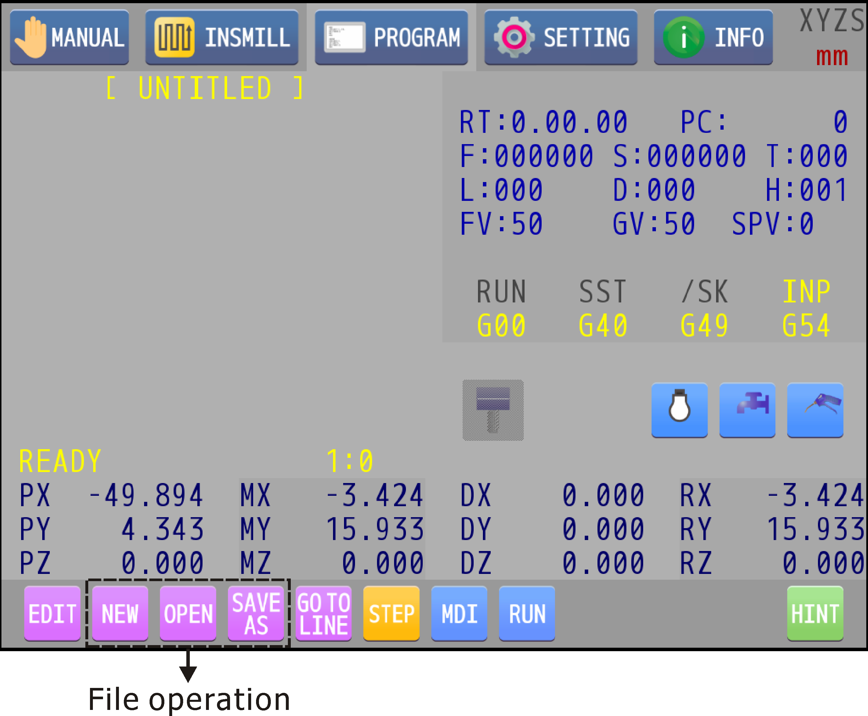
The content of this CNC file is M221, H_, fill in _ with 1 or 0 to turn on or off the external joystick function.
In manual page, user can control the axial movement by using the joystick directly without selecting an axis on UI first. Override can be adjusted through rotating the knob. In addition, press the knob to change the increment step of override, 1 % or 10 %, so that user can get the appropriate feed rate for processing.
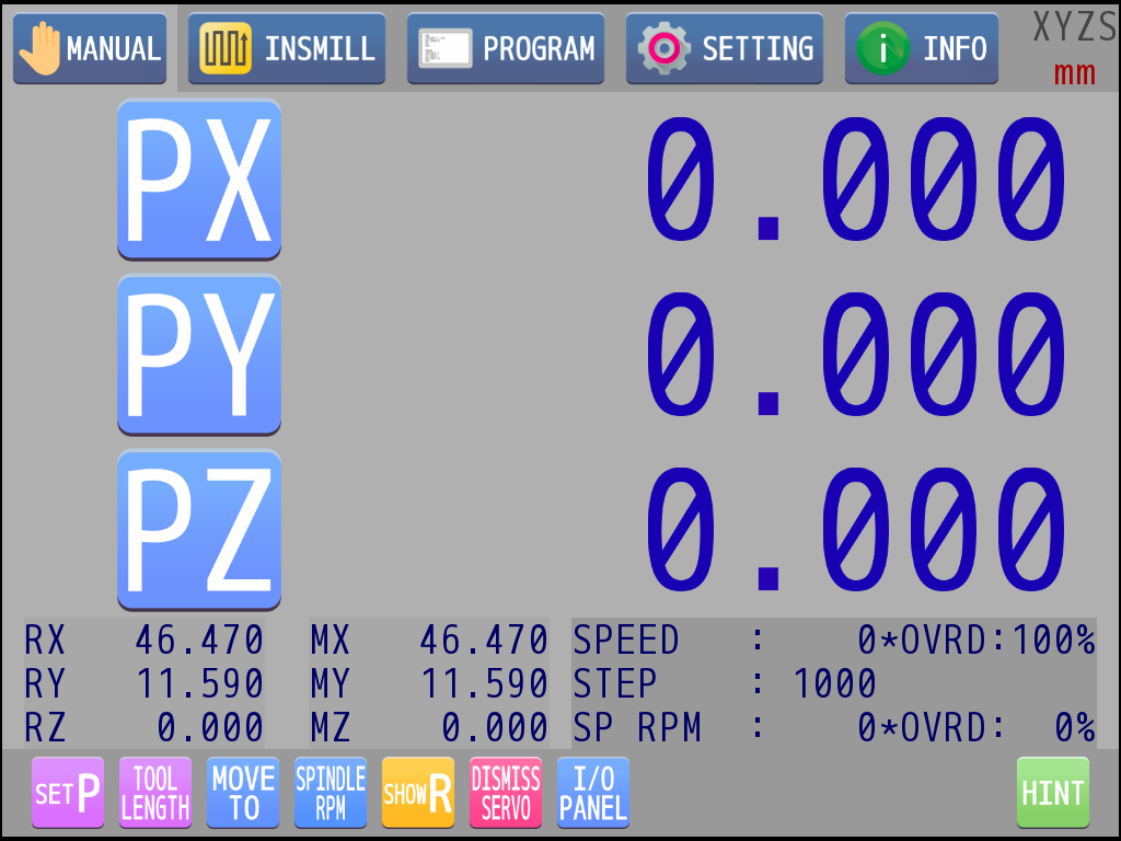
The upper bound of moving speed is limited by JOG speed in axial setting. If JOG speed in axial setting is 2500 mm/min and override percentage is set to 20 %, the actual moving speed is 500 mm/min. In the same way, moving at 25 mm/min when override is 1 %, and so on.