11.3 Drilling, Boring or Tapping Related Can Cycle Instructions
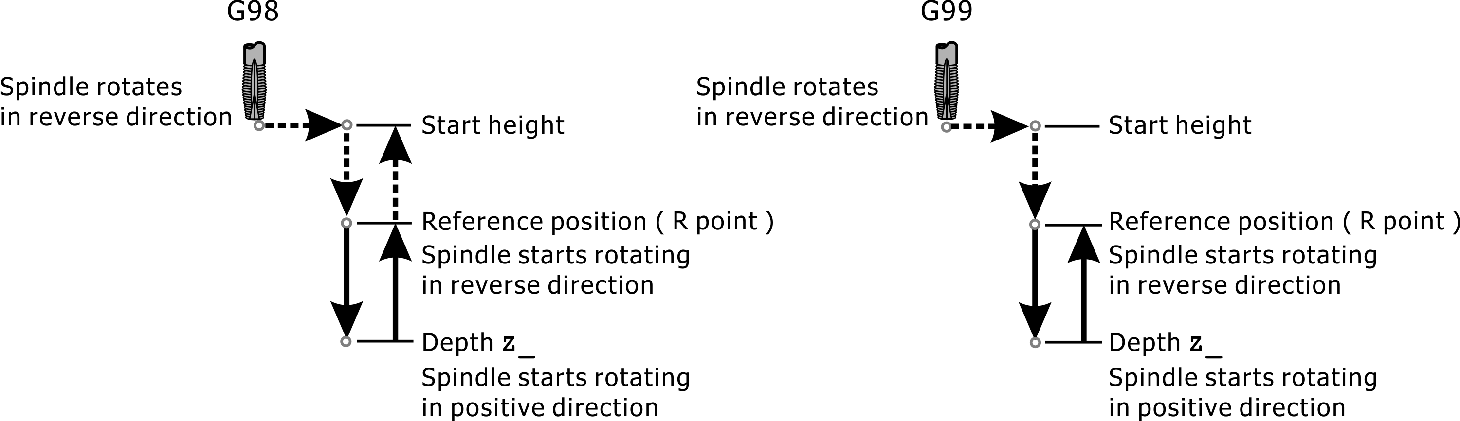
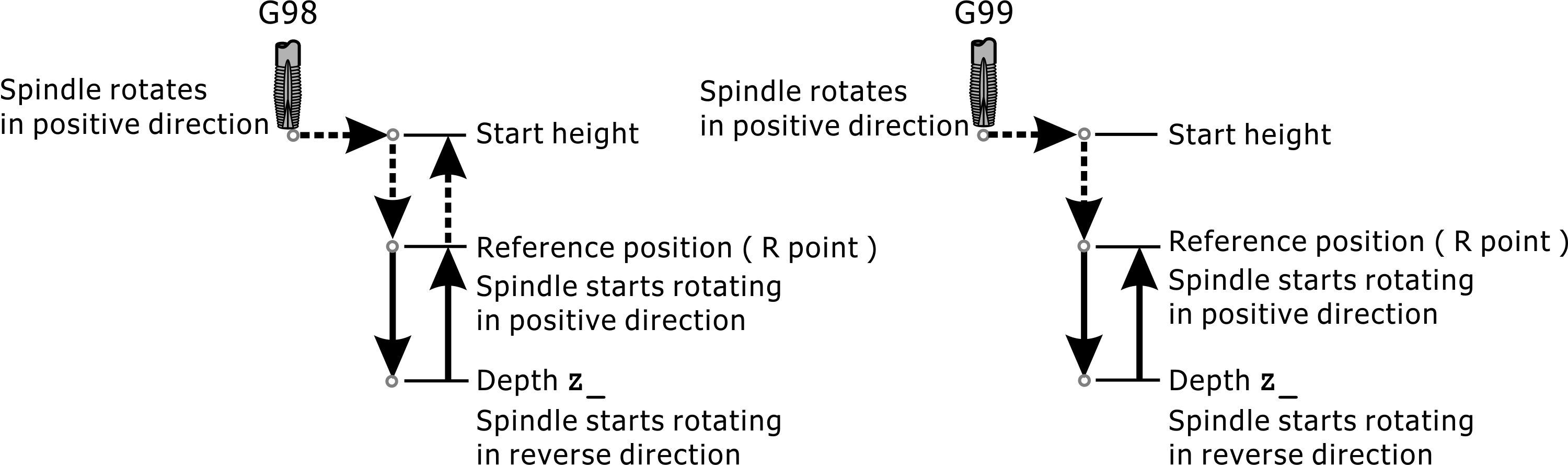
G98/G99: Can cycle command returns original starting height/reference height R point
Format:
G98: Can cycle instruction to return to the original starting height
G99: Can cycle command returns the reference height R point
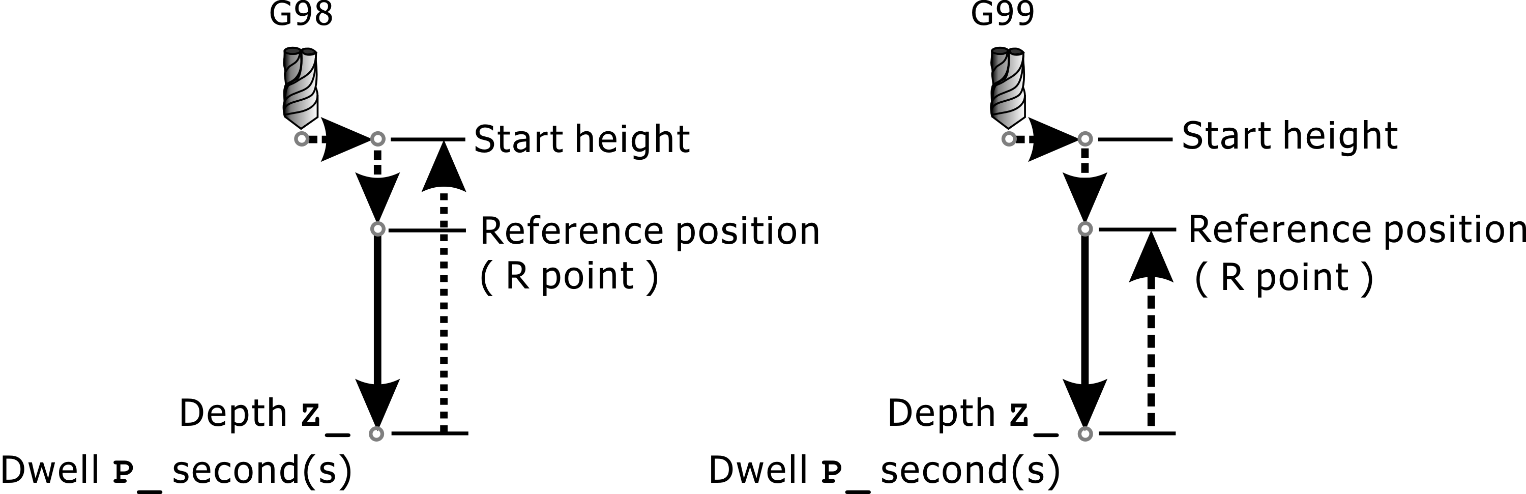
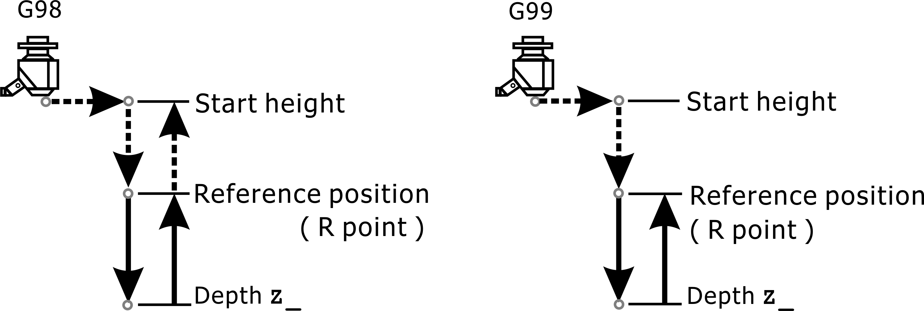
Canned cycles refer to instructions that can be executed cyclically, such as drilling, boring, or tapping. The actions of these instructions are similar. The figure 1 below shows that the tool returns to the original starting height after machining in the G98 command; and in the G99 command, when the action is completed, the tool is returned to the preset reference height R point, as shown in Figure 2 below.
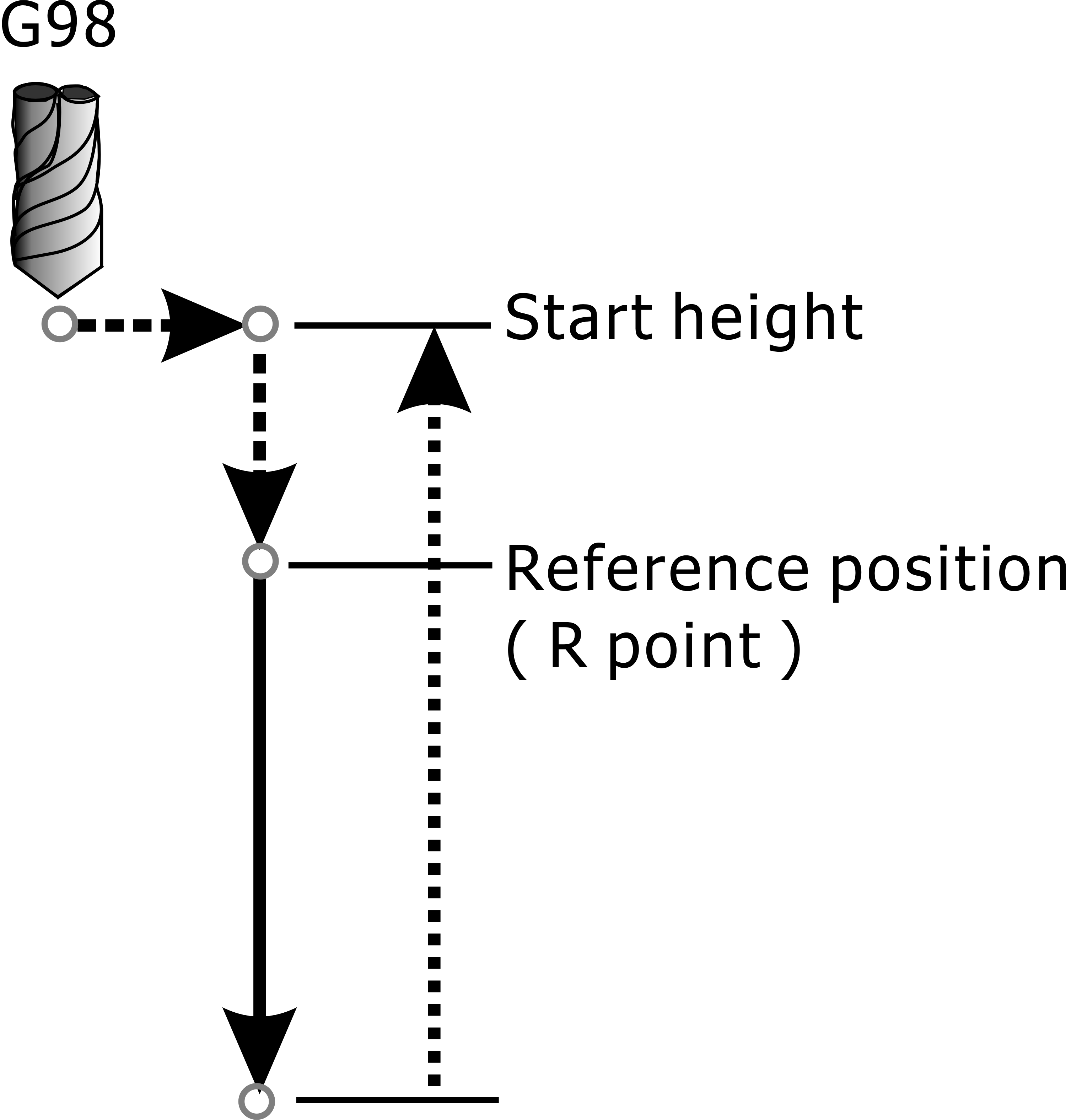
G98: Retract to Star Height
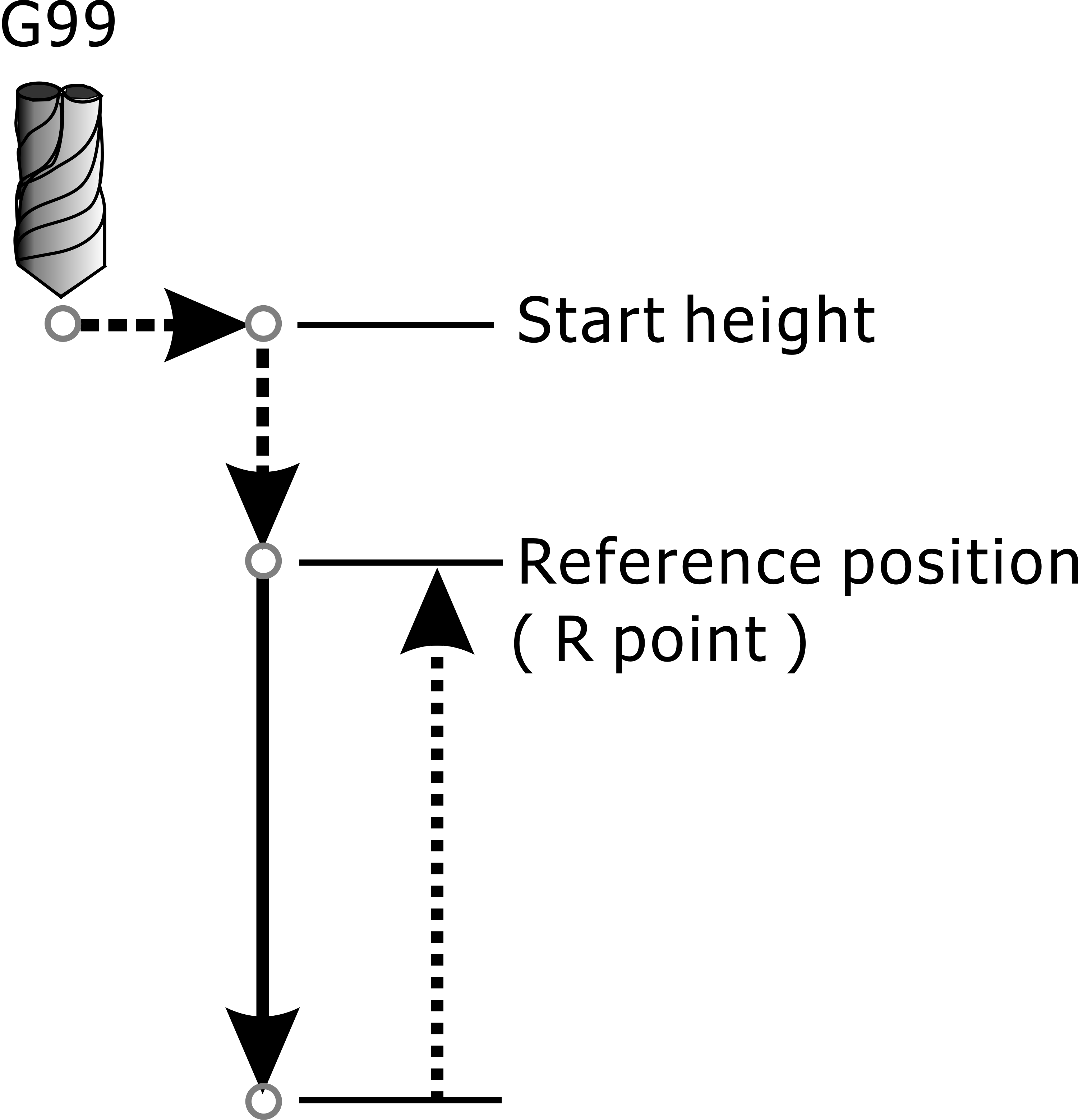
G99: Retract to Reference Position (R point)
When using the can cycle instruction group, it is only necessary to give a cycle machining instruction in the first machining hole position. After that, each repetition machining hole position can be repeatedly processed only by giving its plane position value. Executing G80 cancels the can cycle command; if the Group 01 G code (G00/G01/G02/G03) is also canceled, the can cycle command will be canceled.
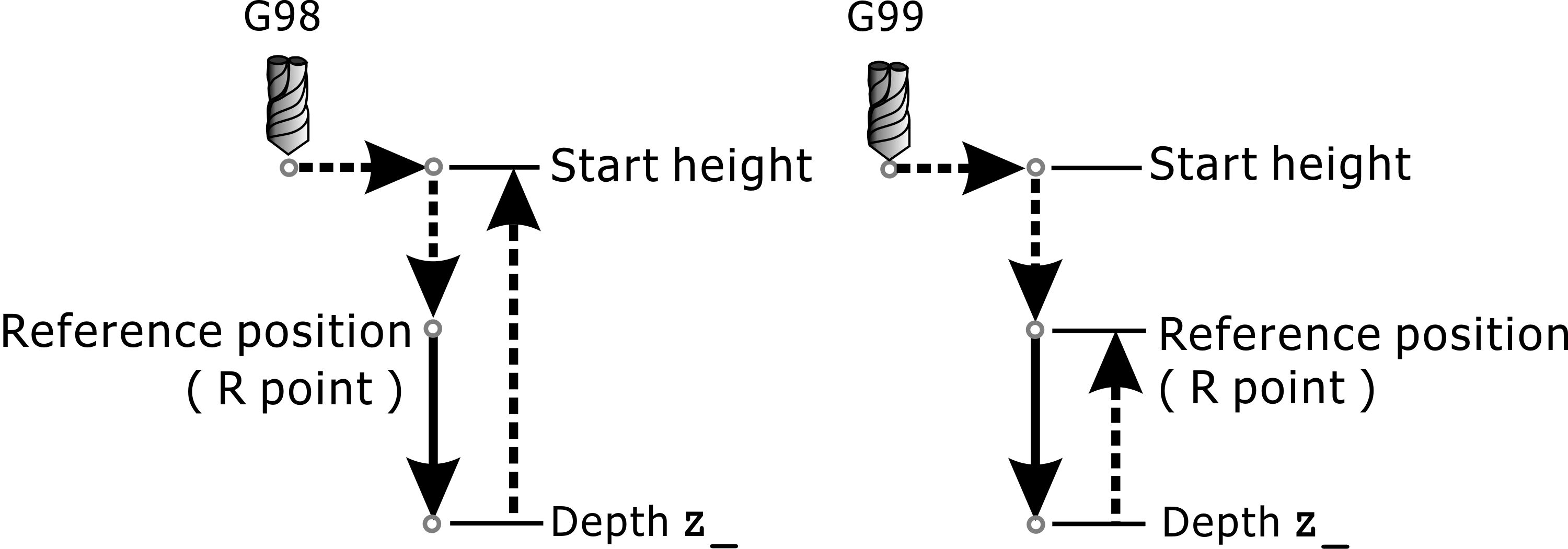
Reference position in the can cycle program command. In G90 absolute coordinate mode, R_ value represents the value of reference position; in G91 relative incremental coordinate mode, R_ value is always positive, representing the original starting height to the reference position. R distance. The machining depth Z value can be defined by G90/G91 respectively: in G90 absolute coordinate mode, Z_ value represents the depth position value; in G91 relative incremental coordinate mode, Z_ value represents the relative position from the reference position R point to the processing depth bottom line Distance, this can be positive or negative. The definitions of the machining cycle instructions in G90/G91 are shown in Figure 1 and Figure 2 below.
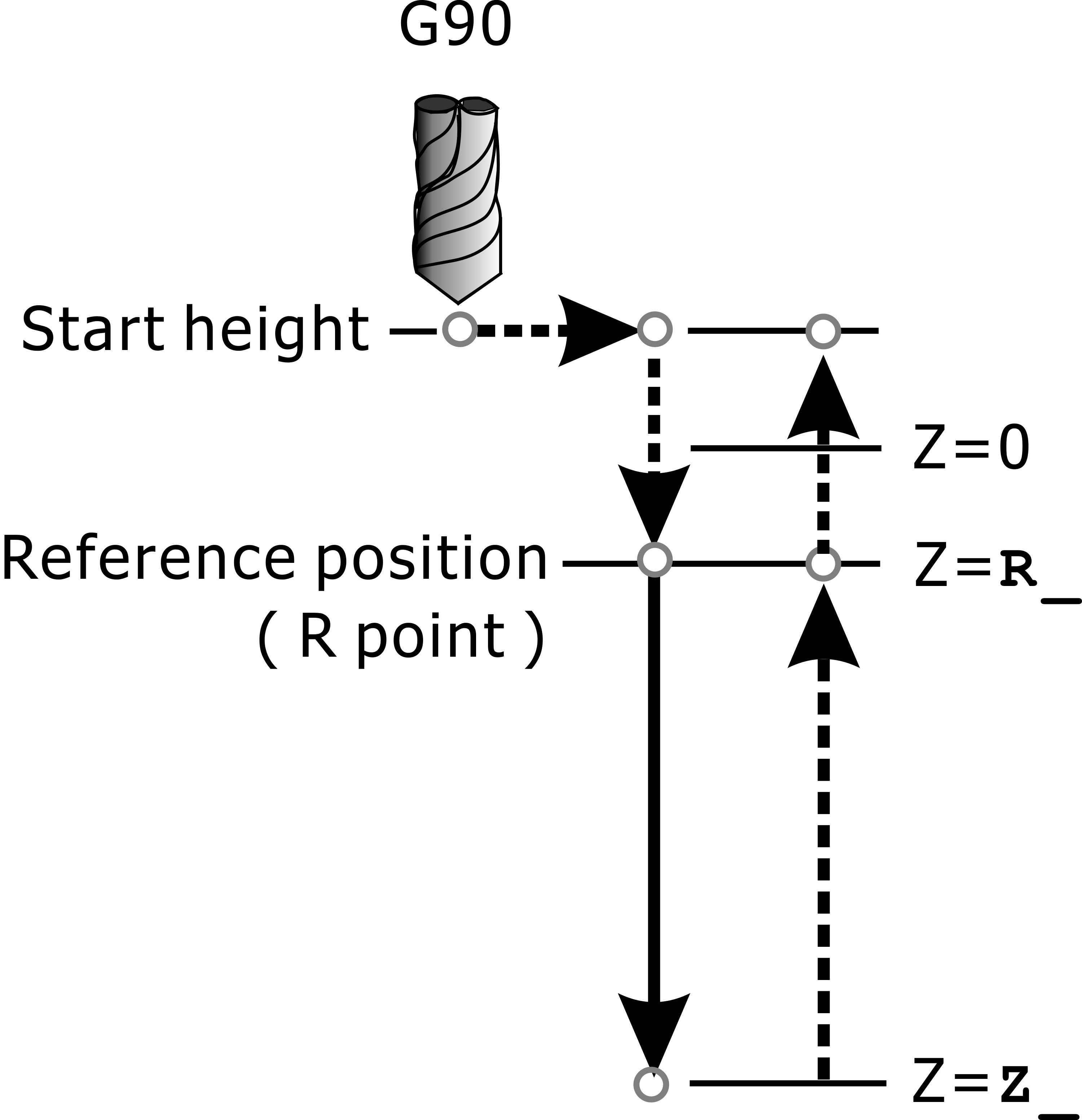
G90: Absolute Position Mode
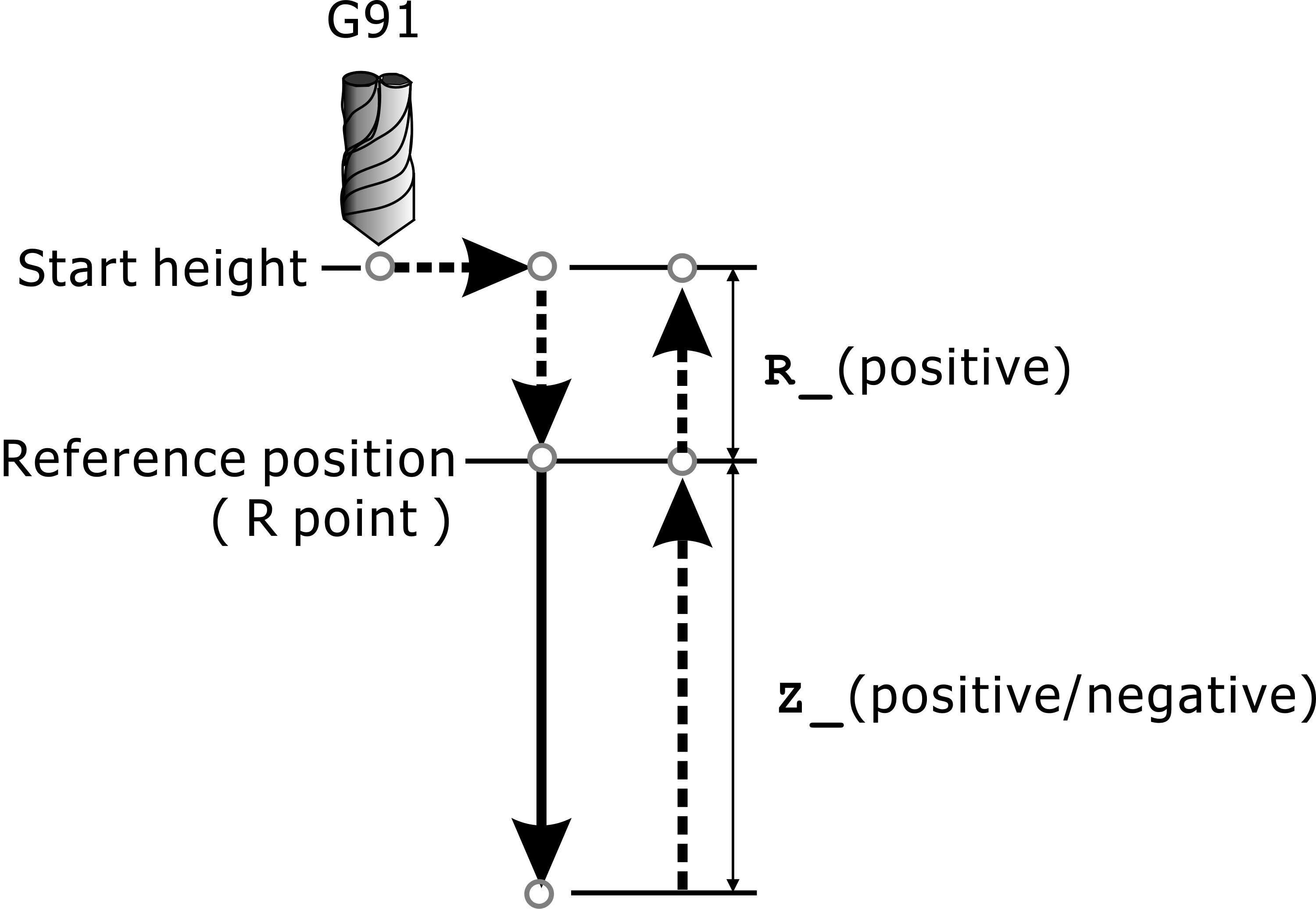
G91: Incremental Value Mode
In addition, in the G91 relative incremental coordinate mode, K_ value can be set for all cycle machining instructions, indicating that the cycle command will be repeated along the straight line or oblique line K_ times (for example: repeat drilling), such as "G91 Gxx Xdx Ydy" Z_ R_ F_ Kk;" indicates that the Gxx (G73~G89) cycle machining instruction is repeated for k times, and the distance between the adjacent two holes on the X and Y axes is dx and dy, respectively.
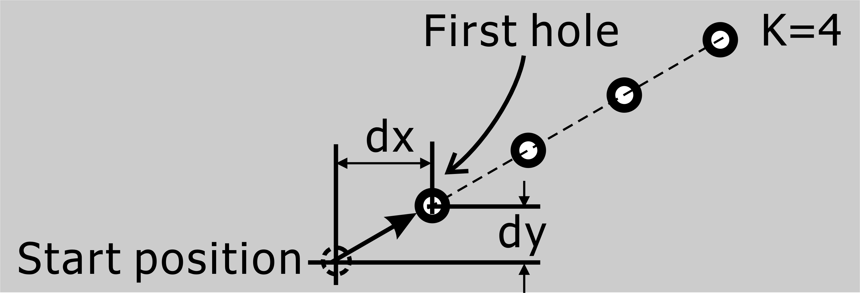
K_ value=4 in G91 Incremental Value Mode
Note 1: |
If the G90 absolute coordinate mode is used, the K_ value will have no effect. The K_ cycle will only be repeated in the same place (X, Y). |
Note 2: |
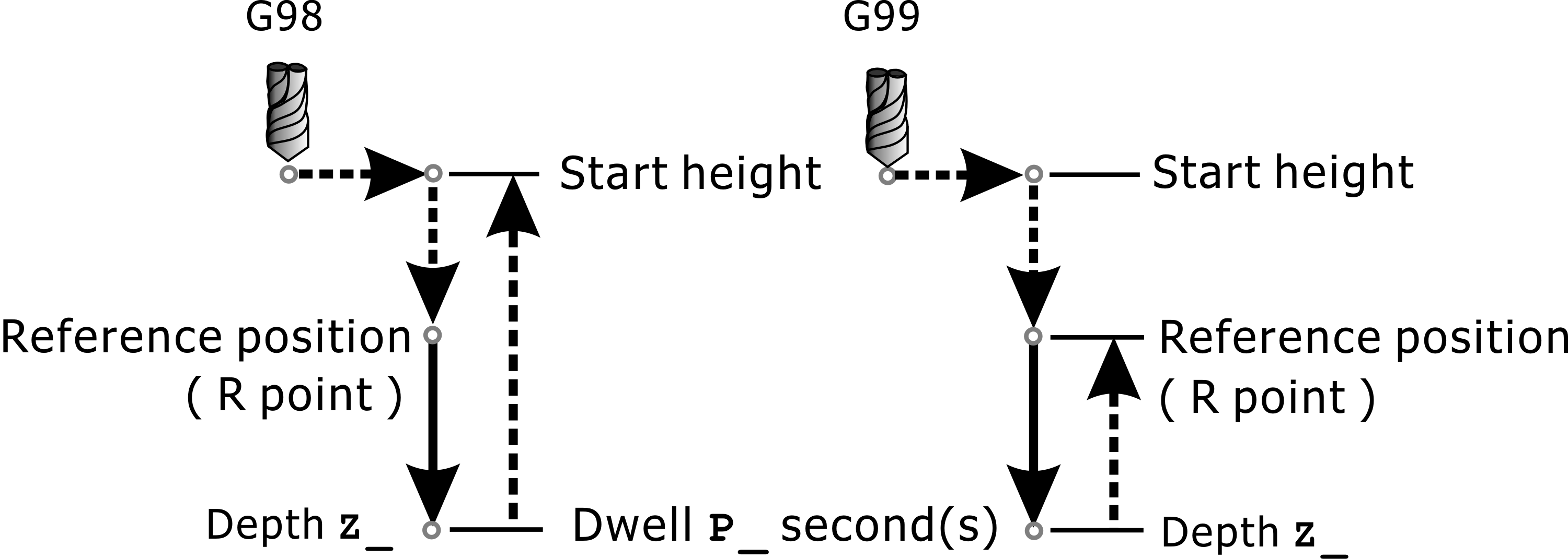
Some cyclic instructions such as G74, G76, G82, G84, G87, G88 and G89 can give P_ value, so that there may be P_ seconds dwell time at the machining depth Z to increase the accuracy of machining depth or The spindle can have a reversed buffer time at the depth Z (as shown below). |
Dwell P_ Seconds
G80: Cancel can cycle instructions
Format:
G80
The cycle command is continuous and effective. Therefore, when executing the same machining mode, it is not necessary to set the command in each block. When the cycle command is completed and no longer used, the machining cycle command should be canceled by G80 to return to the general basic. Instruction status (such as G00, G01, G02, G03, etc.).
G81/G82、G73/G83: drilling can cycle
• G81/G82: Drilling Cycle/Drilling Cycle with Dwell
Format:
G81 X_Y_Z_R_K_F_ ;Drilling cycle
G82 X_Y_Z_R_P_K_F_ ;Drilling cycle with dwell
The G81/G82 command is for general drilling, and simple boring can sometimes use the G81/G82 command. When this command is executed, the drill is quickly positioned to the coordinate position specified by X_Y_, and then it is quickly positioned to point R. Then, the drill bit is drilled down to hole bottom position Z_ at the set feed rate F_, and the tool is quickly retracted to the starting point. (G98 mode) or R point (G99 mode) completes the cycle as shown in the figure below.
Note: |
In the following illustration, the solid line indicates the feed rate F_, and the dashed line indicates the speed of rapid positioning (G00). |
G81: Drilling Cycle
The G82 command dwell time P_ seconds at the bottom of the hole, all other machining operations are the same as G81; G82 dwell the tool for a few seconds after cutting to the bottom of the hole, which can improve the bottom accuracy of blind hole, column hole and cone hole.
G82: Drilling Cycle with Dwell
• G73/G83: High Speed Peck Drilling Cycle/Peck Drilling Cycle with Chip Breaking
Format:
G73 X_Y_Z_R_Q_K_F_ |
;High Speed Peck drilling cycle |
G83 X_Y_Z_R_Q_K_F_/X_Y_Z_R_I_J_K_L_F_ |
;Peck drilling cycle with chip breaking |
G73/G83 were complicate drilling boring can cycle,and it uses peck drilling,each peck drilling has chip retrace. The peck drilling for drilling can cut off chip and coolant can get in hole, and has better cooling and lubricate effect.
When G73 executed, drilling tool moves to position X_Y_ rapidly, then moves to reference high position R_, then drilling tool start drilling a distance Q_ with feed F_ (Q_ must positive value), then retrace a d distance rapidly, repeat this cycle until reach hole bottom position z_, the retrace distance d is fix value in G73, and d was defined in item of "Setting→ Cancycle Parameters". d as below diagram shows.
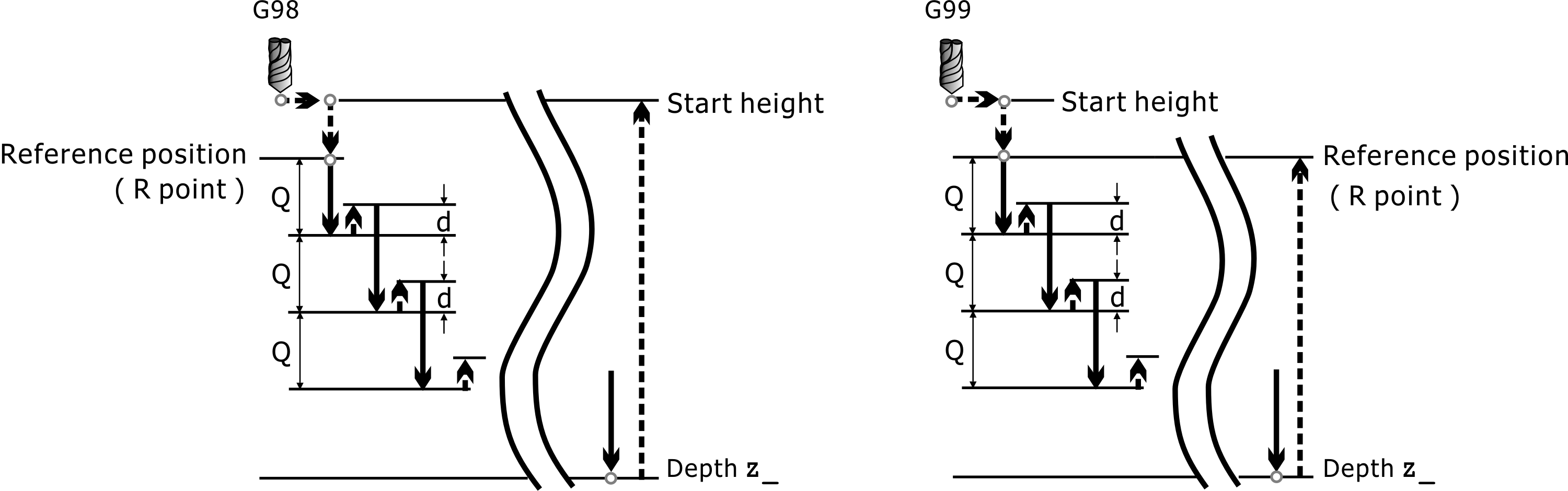
G73: High Speed Peck Drilling Cycle
As shown in the figure below, G83 command operation is similar to that of G73. The difference is that when retracting, G83 command retracts to the reference height R_ at every retraction, so that the chip can be taken out of the hole to prevent the chip from inserting the groove plug increases the drilling resistance or makes the cutting agent unable to reach the cutting edge. The G83 is suitable for deep-hole drilling.
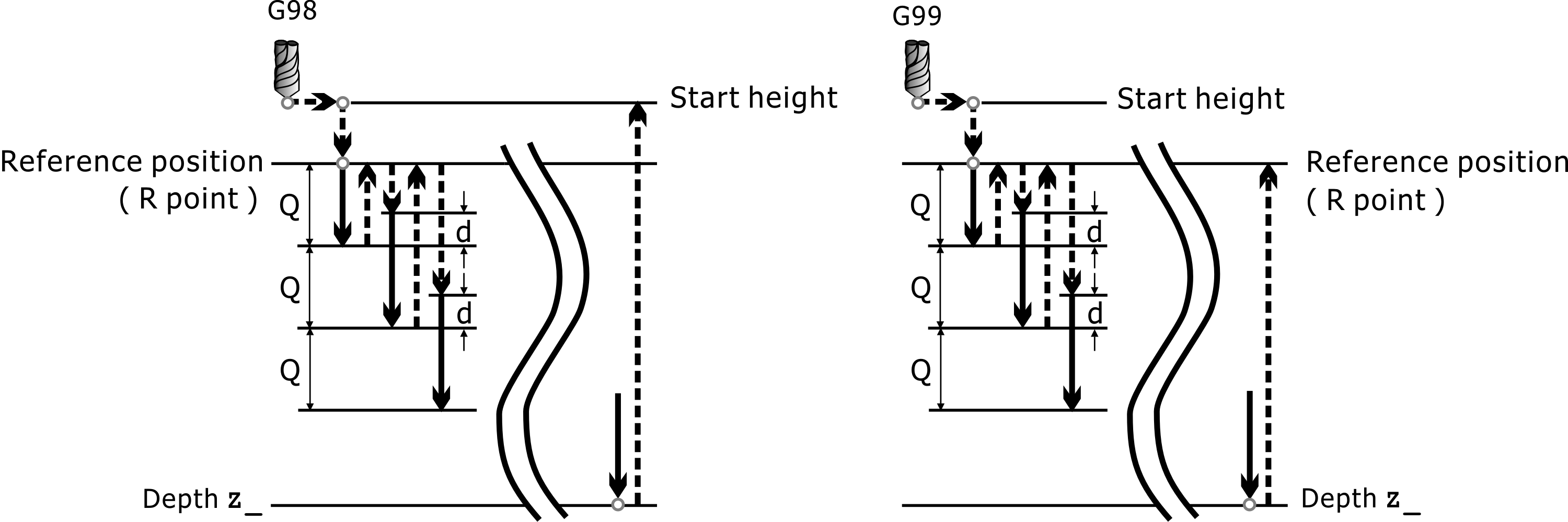
G83: Peck Drilling Cycle with Chip Breaking
The G83 instruction format is: G83 X_Y_Z_R_Q_K_F_ and G83 X_Y_Z_R_I_J_K_L_F_, The description is as follows:
Format 1: G83 X_Y_Z_R_Q_K_F_
Format 2: G83 X_Y_Z_R_I_J_K_L_F_
I: Initial depth of feed
J: Reduce the depth of each feed
K: Minimum feed depth
L: Repeat holes
The feed depth at the first feed is the value specified by I, and the feed depth at each feed will reduce the value specified by J, but the feed depth must not be less than the value specified by K, since K is used in Specify the minimum feed depth, so change the number of repeat holes to L.
Usage rule:
If I is not set, use first format 1.
If I is set: use second format 2.
If I value is 0, drilling hole to bottom non stop.
If K value is 0, the minimum infeed depth is not specified, and each infeed depth is the value specified by I.
G85/G86, G76/G87, G88, G89: Boring can cycle
• G85/G86: Boring Cycle/Boring Cycle with Spindle Stop
Format:
G85 X_Y_Z_R_K_F_
G86 X_Y_Z_R_K_F_
This command is applicable to the reaming hole. When the G85 instruction is executed, it is as shown in the following figure. The reamer is quickly positioned to the designated coordinate position X_Y_, and then quickly positioned to the reference height R_, and then re-hinge to the specified hole seating position Z_ at the specified feed rate F_, still specified. The feed rate F_ rises upwards.
G85: Boring Cycle
When the G86 command is executed, the spindle will stop rotating after reaching the machining depth Z_, and will return to the original starting height (G98 mode) or the reference position R_ (G99 mode) at G00 speed, and then the spindle will resume clockwise rotation.
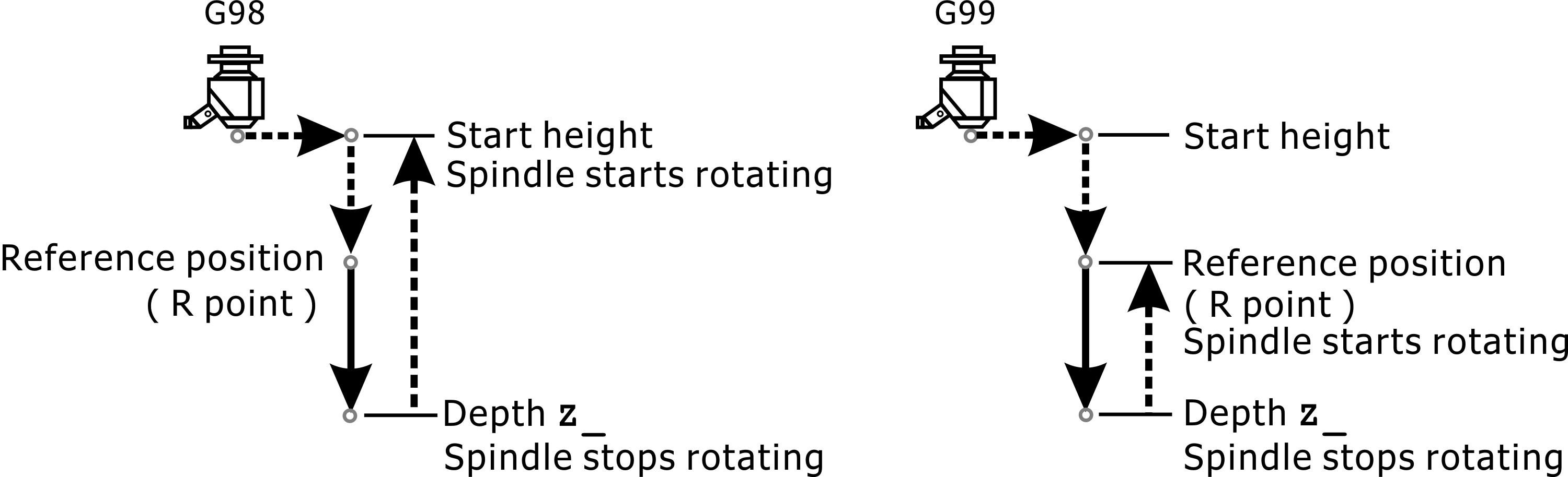
G86: Boring Cycle with Spindle Stop
• G76/G87: Fine Boring Cycle/Fine Back Boring Cycle
Format:
G76 X_Y_Z_R_Q_P_K_F_
G87 X_Y_Z_R_Q_P_K_F_
The G76/G87 precision boring holes are all axially specified spindle stops and are therefore precision boring holes. When G76 command is executed, the boring tool is quickly positioned to coordinate point X_Y_, and then it is quickly positioned to the reference height R_ point. After the hole is drilled to the specified depth Z_ at the specified feed rate F_, the spindle orientation is stopped and the tool tip is pointed to after the fixed direction, the center of the boring tool is offset by the Q_ value, so that the tool tip leaves the machining hole surface, and the boring tool is quickly positioned outside the hole to avoid scratching the hole surface. After the boring tool is returned to the original starting height (G98 mode) or the reference height R_ point (G99 mode), the tool center is quickly positioned to return to coordinate X_Y_, and the spindle resumes forward rotation as shown in the following figure.
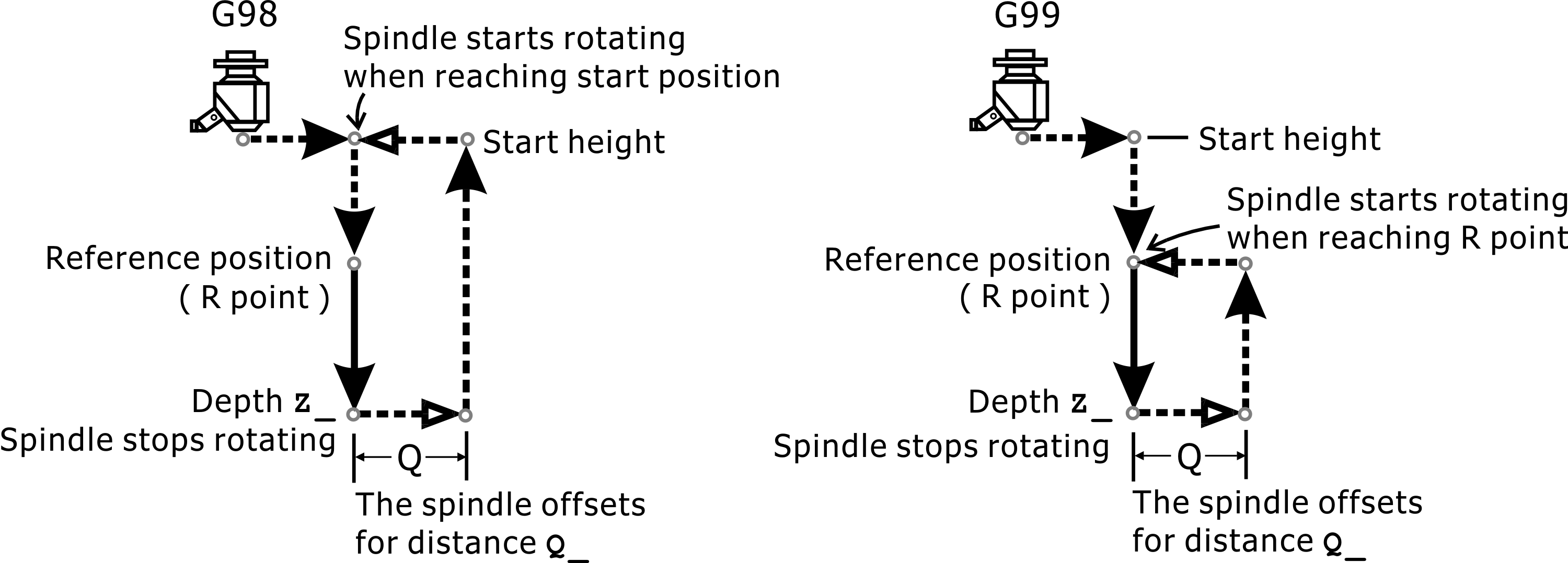
G76: Fine Boring Cycle
Note: |
The offset Q_ must be positive and its value must not be too large to avoid collisions with the workpiece. |
When G87 command is executed, the back boring cutter is quickly positioned to the specified coordinate position X_Y_, the spindle orientation is stopped, the tool tip points in a fixed direction, and the center of the back boring cutter is offset by a small distance Q_ so that the tool tip leaves the machining hole surface. Afterwards, under the tool, to prevent the tool edge from scratching the newly processed hole surface. When the tool moves to the reference height R_ hole bottom, it is offset by the Q_ distance in the original angular direction and then the spindle is resumed to rotate, and the counterboring is started at the specified feed rate F_ to Z_ height. After that, the spindle is stopped orientated, and the tool nose is offset from the machining hole surface to the distance Q_, the tool is raised to the original height, and after the Q_ distance is shifted toward the original angle, the cycle is returned to the original position X_Y_.
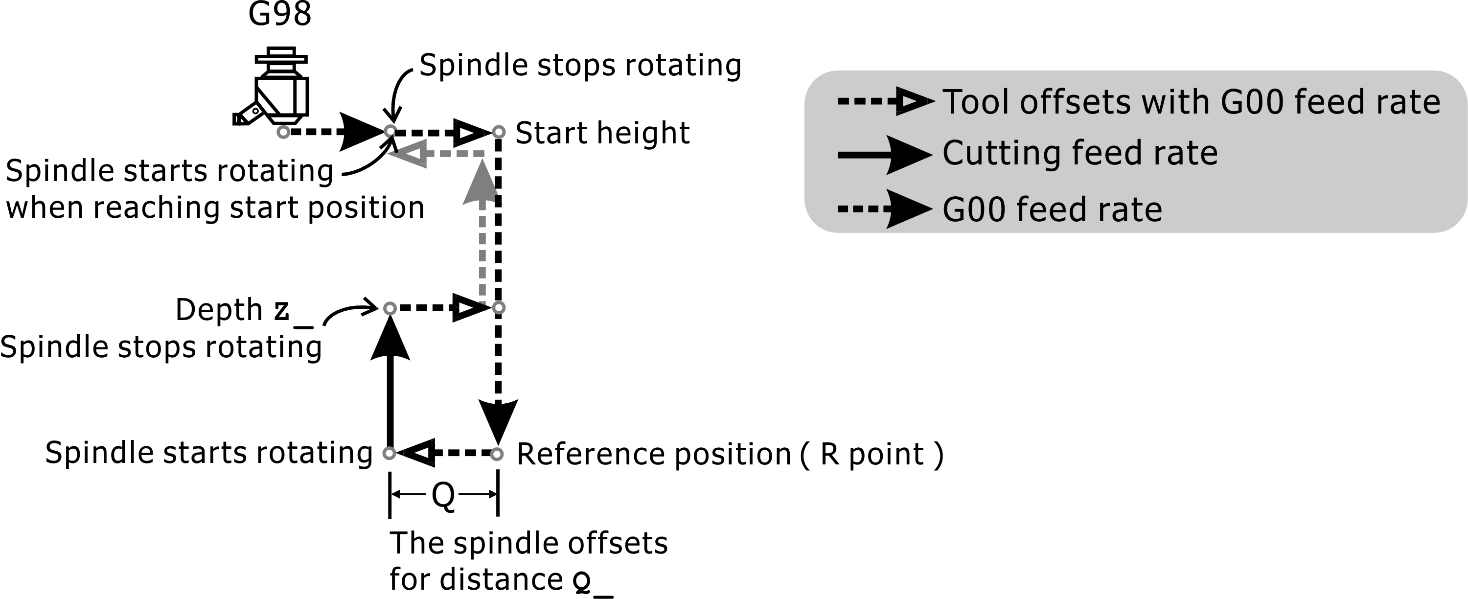
G87: Fine Back Boring Cycle
Note: |
The reference position R of the G87 fin reverse boring and the depth of the program Z_ value are different from other cyclic machining. The reference position R point is at the lowest point, and the program Z_ value depth is above the reference position R point. Because its reference position R point is at the lowest point, G87 command is not allowed to execute in G99 mode (back to reference position R point). |
• G88: Boring Cycle with Dwell and Manual Retraction
Format:
G88 X_Y_Z_R_P_K_F_
When G88 command is executed, P_ seconds will be paused after machining to Z_ value depth and the spindle will stop rotating. At this time, the operator can safely retreat the tool to the reference height R_ point or more after manually offsetting, and then use the mechanical panel to leave the manual control mode. , If the reference position R_ value or more is not reached, there will be a warning dialog box, and manual control cannot be closed. In G98 mode, the tool will continue to be raised to the original starting height; if it is in G99 mode, the tool will no longer move. The X, Y coordinates do not return to the X_, Y_ positions specified by G88.
Note: |
After the program determines that the tool is already at the reference position R_ point or more, it will automatically resume the forward rotation of the spindle. Please remove the head and hand from the spindle to ensure safety! |
G88: Boring Cycle with Dwell and Manual Retraction
• G89: Boring Cycle with Dwell
Format:
G89 X_Y_Z_R_P_K_F_
When G89 command is executed, the spindle will feed back to the reference height R_ at the feed speed F_ after machining to the Z_ value depth of the program and dwell for P_ seconds. In this case, if the G98 mode is used, the spindle will quickly go to the original starting height again, otherwise it stops moving.
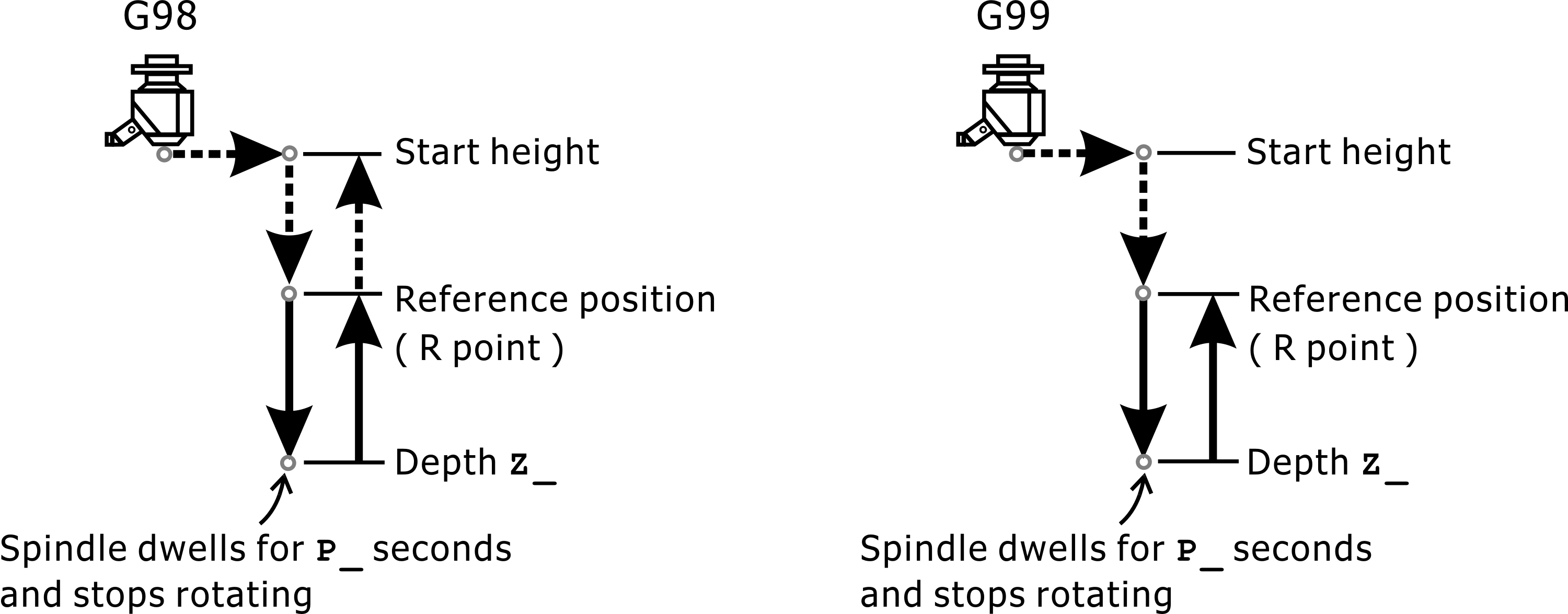
G89: Boring Cycle with Dwell
G74/G84: Tapping can cycle
Format:
G74 X_Y_Z_R_P_K_F_: Tapping cycle (Left hand)
G84 X_Y_Z_R_P_K_F_: Tapping cycle (Right hand)
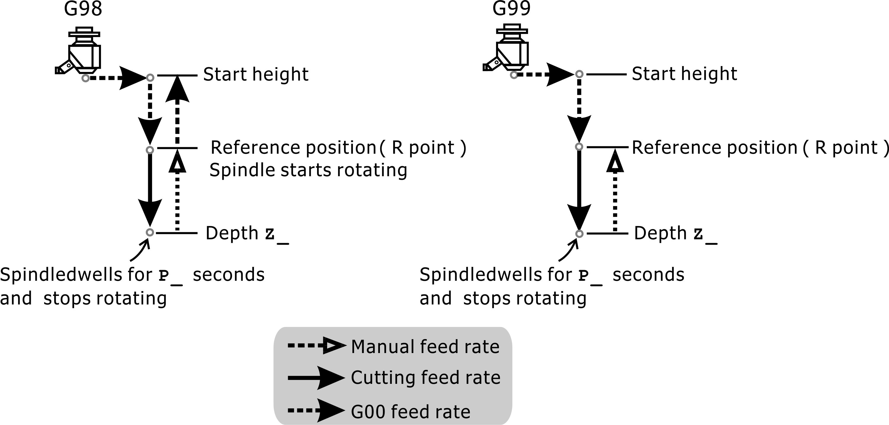
Since the G74 command is used for left-hand tapping, it is necessary to reverse the spindle (M04) before executing the G74 command. When executing the G74 command, the tool is quickly positioned to the specified coordinate position X_Y_, and then quickly positioned to the reference height R_ point. Then, after tapping at the feed rate F_ to the hole seating position Z_, the spindle changes to the positive rotation and simultaneously to the Z axis. The positive direction retracts to the reference height R_ point, and the spindle reverts to the original reversal after retracting to the R_ point.
G74: Tapping Cycle (Left-Hand)
The G84 command is used for right-handed tapping. Therefore, the spindle must be rotated forward (M03) before executing the G84 command. When executing the G84 command, the tool is quickly positioned to the specified coordinate position X_Y_, and then quickly positioned at the reference height R_. Then, after tapping at the feed rate F_ to the hole seat position Z_, the spindle is reversed and simultaneously to the Z axis. The positive direction retracts to the reference height R_ point, and the spindle returns to the original positive rotation after retracting to the R_ point.
G84: Tapping Cycle (Right-Hand)
The Q value can be added to the G74/G84 command to perform drilling and tapping. The steps are as follows:
1. X, Y axis positioning.
2. Position the Z axis to the reference position R_ point.
3. Tap to depth of Q_ value and then return to reference position R_ point.
4. Tapping to 2Q_ depth, then back to reference position R_.
5. Tapping to 3Q_ depth, then back to reference position R_.
6. According to this order tapping to the depth of demand.
• Rigid Tapping
Format:
M29 S_
M03
G84 X_Z_R_F_
For rigid tapping, the spindle must be equipped with an encoder and the spindle drive can output a combination of low speed and high torque to perform the operation. Please make sure that the above mentioned equipment can use rigid tapping.
If only a general AC inverter motor is used instead of the spindle drive, the tapping depth will be different depending on the speed characteristics of the inverter motor and the tapping parameter setting, and the tapping may be too deep or slightly shallow. Please contact the original in advance. Machinery plant confirmation.
To use rigid tapping, you must first set the M29 S_ command in preparation for rigid tapping and specify the tapping speed. This speed can not be too fast, and the mechanical manufacturer limits its maximum speed in the advanced parameters. If the given S_ is greater than the set value in the advanced parameters, it will be replaced by the set value in the advanced parameters.
Note: |
The M code and S code of the rigid tapping mode remain active in the cycle command until the command cancels. |
If there is a high and low speed shift on the spindle, before performing rigid tapping, be sure to shift the gear set to the specified rigid tapping gear before using it with the rigid tap speed adjustment to obtain the correct pitch. Gearless gear sets are gear-free. The calculation of the rigid tapping distance differs depending on the G94 and G95 modes:
1. |
In G94 mode, F_ represents the feed distance per minute, S_ represents the rotation speed per minute, so F/S represents the distance per feed, which is equal to the desired pitch. If F=100 mm/min, S=200 rpm, the resulting pitch is equal to 100/200=0.5 mm. The processing program can be edited as follows: |
G90 G0 X0 Y0 Z0 ; Move to the center of the workpiece and Z axis
G49 G54 G94 ; Choose G94 Mode
M29 S200 ; Initiate rigid tapping function S=200 rpm
M03 ; Spindle rotation
G84 X0 Y0 Z-10. F100 ; Starting tapping depth 10 mm; pitch=100/200=0.5 mm
G80 ; End the tapping cycle
M30
2. |
In G95 mode, F_ represents the feed distance per revolution, which is the desired pitch. If F=3 mm/rev, the resulting pitch is F=3 mm irrespective of the spindle speed. This F_ value can have decimals, so it is also suitable for rigid taps less than 1 mm pitch. This machining program can be edited as follows: |
G90 G0 X0 Y0 Z0 ; Move to the center of the workpiece and Z axis preparation
G49 G54 G95 ; Select G95 mode
M29 S200 ; Initiate rigid tapping function S=200 rpm
M03 ; Spindle positive spin
G84 X0 Y0 Z-10. F0.5 ; Starting rigid tapping depth 10 mm; pitch = 0.5 mm
G80 ; End rigid tapping cycle
M30
Note: |
In the program, G84 X0 Y0 Z-10. F0.5; F0.5 directly indicates the pitch of 0.5 mm, which makes the program easier to read. |
Special application of can cycle instructions (K0)
In the can cycle command line, if K0 is input, this line will not be executed and only used to load the various parameters of the can cycle, so that the following position command can be used to execute the can cycle.
Example as below:
G00 Z30.
G81 Z-20.R1.F500 K0 ; This line will not execute a can cycle. It is only used to load depth, reference position, feedrate
X10. ; In X10. position, execute "Depth -20. Reference position 1. Machining cycle at feedrate 500"
X20. ; In X20. position, execute "Depth -20. Reference position 1. Machining cycle at feedrate 500"
X30. ; In X30. position, execute "Depth -20. Reference position 1. Machining cycle at feedrate 500"