8.3 Interfaces on ESPU
There are interfaces of spindle, hand wheel, linear encoder and digital input/output on ESPU. It could control direction and velocity of spindle, even do rigid tapping or positioning if the driver is allowed to. It also receives the signals from an external handwheel, linear encoder and provides 8 digital inputs/outputs. The EtherCAT interface is used to connect to the host.

PWR: Power terminal block
PWR provides the connection to DC 24V. Please use the same power source of M83. Please make sure the voltage polarity is correct before turning this on.
Pin |
Explain |
24V |
Positive electrode of DC 24V |
24G |
Negative electrode of DC 24V |

PWR Placement Drawing
F.G.: Ground terminal
Connect ground terminal to the grounding copper plate in the distribution box via the grounding wire to protect ESPU.

F.G. Placement Drawing
X1~X8: Digital input terminal block
Digital input terminal block has 8 digital inputs, 1 input common point (COM) and DC 24V input E24V and E24G for external IO on SP and MPG.
8 input points can connect to whether the 24V or 0V, PNP or NPN connection. Each input has a LED indicator to tell the status of this input.
Please be aware: Only use NPN or PNP connection in one time. The voltage source of input common point (COM) should not be the same as the PWR, or it would lose the function of isolated design.
Pin |
Definition |
Explain |
Corresponding LED indicator |
X1 |
Digital input point 1 |
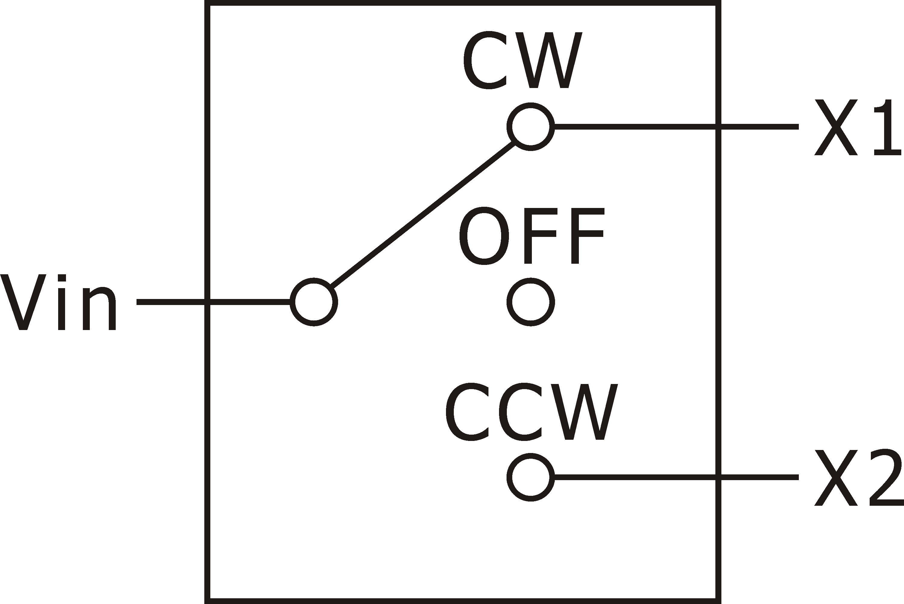
Spindle CW signal in manual mode |
X-1 |
X2 |
Digital input point 2 |
Spindle CCW signal in manual mode |
X-2 |
X3 |
Digital input point 3 |
Status input of spindle high/low gear. Contact when in high gear. |
X-3 |
X4 |
Digital input point 4 |
External handshake M code input point |
X-4 |
X5 |
Reserved |
Reserved input point |
X-5 |
X6 |
Reserved |
Reserved input point |
X-6 |
X7 |
Reserved |
Reserved input point |
X-7 |
X8 |
Reserved |
Reserved input point |
X-8 |
COM |
Common point of digital inputs |
NPN connection: External 24V PNP Connection: External 0V |
NA |
E24V |
External 24V |
It is connected to VI of SP and MPG, use to provide SP, MPG external 24V |
NA |
E24G |
External 24V voltage reference point |
It is connected to VG of SP and MPG, use to provide SP, MPG external 0V |
NA |

X1 and X2 Drawing

X1~X8 Placement Drawing
Y1~Y8: Digital output terminal block
Y1~Y8 are 8 relay outputs with A, B, COM contacts. Output contacts are only allowed to connect with magnetic contactor or coil of pneumatic valve, when the rated output voltage is AC220V, an spark killer must be put on to avoid noise and interference. Each output point has a corresponding LED indicator to tell the status.
Output terminal |
Definition |
Explain |
Corresponding LED indicator |
Y1 |
Digital output point 1 |
Lamp output point (NO point) |
Y-1 |
Y2 |
Digital output point 2 |
coolant output point (NO point) |
Y-2 |
Y3 |
Digital output point 3 |
air blower output point (NO point) |
Y-3 |
Y4 |
Digital output point 4 |
External handshake M code output point (NO point) |
Y-4 |
Y5 |
Digital output point 5 |
Z axis brake |
Y-5 |
Y6 |
Digital output point 6 |
Green light-running |
Y-6 |
Y7 |
Digital output point 7 |
Yellow light-standby |
Y-7 |
Y8 |
Digital output point 8 |
Red light-alarm |
Y-8 |

Y1~Y8 Placement Drawing
IN, OUT: EtherCAT Communication Connector
- IN:EtherCAT cable IN
Connect upstream to the previous EtherCAT device.
- OUT:EtherCAT cable OUT
Connect downstream to the next EtherCAT device.

IN and OUT Placement Drawing
SP: Spindle connector
The spindle connector is connected to the spindle driver with a 26 PIN 3M-SCSI connector. This interface includes directions/velocity command, encoder feedback and some assisting I/Os.
Pin |
Definition |
Explain |
Corresponding LED indicator |
1 |
Velocity command |
±10V analog output |
NA |
2 |
Velocity command reference point |
±10V analog output reference point |
NA |
3 |
Spindle CW |
Photocoupler output point +, common conduction to output signal |
NA |
4 |
Spindle CCW |
Photocoupler output point +, common conduction to output signal |
NA |
5 |
Rigid tapping |
Photocoupler output point +, common conduction to output signal |
NA |
6 |
Spindle positioning |
Photocoupler output point +, common conduction to output signal |
NA |
7 |
Common point of output signals |
Photocoupler output point - |
NA |
8 |
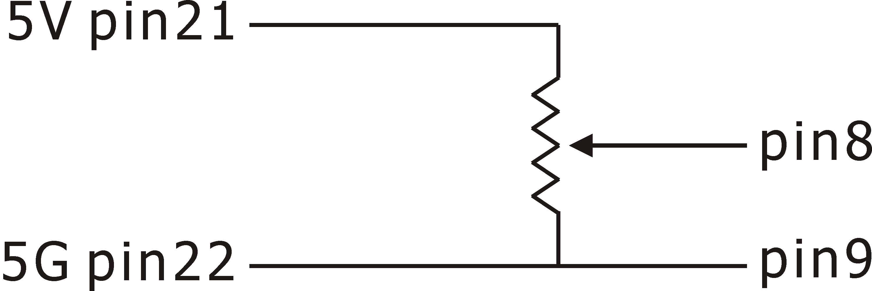
Spindle override analog input |
Adjust spindle override in manual mode |
NA |
9 |
analog input reference point |
Analog input reference point |
NA |
10 |
Spindle alarm |
Input point, PNP or NPN input |
NA |
11 |
Spindle zero speed |
Input point, PNP or NPN input |
NA |
12 |
Spindle speed arrival |
Input point, PNP or NPN input |
NA |
13 |
Spindle positioning finish |
Input point, PNP or NPN input |
NA |
14 |
Common point of input signals |
Input point NPN connection: External 24V connection Input point PNP Connection: External 0V connection |
NA |
15 |
A+ |
Spindle encoder A+ signal input |
NA |
16 |
A- |
Spindle encoder A- signal input |
NA |
17 |
B+ |
Spindle encoder B+ signal input |
NA |
18 |
B- |
Spindle encoder B- signal input |
NA |
19 |
Z+ |
Spindle encoder Z+ signal input |
NA |
20 |
Z- |
Spindle encoder Z- signal input |
NA |
21 |
5V |
Power supply for spindle encoder (Power: 1W per axis) |
NA |
22 |
5G |
5V Power reference point |
NA |
23 |
VI |
External 24V, provided by E24V pin of Digital input terminal block |
NA |
24 |
VG |
External 24V power reference point, connect with E24G pin of Digital input terminal block |
NA |
25 |
NC |
Empty |
NA |
26 |
NC |
Empty |
NA |

pin8, pin9, pin21, pin22 Drawing

SP Placement Drawing
MPG: Handwheel connector
The connector is connected to hand wheel with a 14 PIN 3M-SCSI connector. This interface includes axial selection, multiply rate selection and handwheel counter feedback.
Pin |
Definition |
Explain |
Corresponding LED indicator |
1 |
X axis selection |
Input point, PNP or NPN input |
NA |
2 |
Y axis selection |
Input point, PNP or NPN input |
NA |
3 |
Z axis selection |
Input point, PNP or NPN input |
NA |
4 |
Multiply rate selection X10 |
Input point, PNP or NPN input |
NA |
5 |
Multiply rate selection X100 |
Input point, PNP or NPN input |
NA |
6 |
Common of handwheel signals |
Connect to the COM on handwheel |
NA |
7 |
A+ |
Hand wheel A+ signal input |
NA |
8 |
A- |
Hand wheel A- signal input |
NA |
9 |
B+ |
Hand wheel B+ signal input |
NA |
10 |
B- |
Hand wheel B- signal input |
NA |
11 |
Handwheel indicator + |
Connect to the indicator + on handwheel |
NA |
12 |
Handwheel indicator - |
Connect to the indicator - on handwheel |
NA |
13 |
5V |
Hand wheel power (Power: 1W) |
NA |
14 |
5G |
5V Power reference point |
NA |

MPG Placement Drawing
SCALE:Linear encoder connector
The SCALE connector is connected to the linear encoder with a 15 PIN D-SUB connector.
Pin |
Definition |
Explain |
Corresponding LED indicator |
1 |
A+ |
Linear encoder A+ signal input |
NA |
2 |
A- |
Linear encoder A- signal input |
NA |
3 |
B+ |
Linear encoder B+ signal input |
NA |
4 |
B- |
Linear encoder B- signal input |
NA |
5 |
Z+ |
Linear encoder Z+ signal input |
NA |
6 |
Z- |
Linear encoder Z- signal input |
NA |
7 |
NC |
Empty |
NA |
8 |
NC |
Empty |
NA |
9 |
5V |
Power supply for linear encoder (Power: 1W per axis) |
NA |
10 |
NC |
Empty |
NA |
11 |
5G |
5V Power reference point |
NA |
12 |
NC |
Empty |
NA |
13 |
NC |
Empty |
NA |
14 |
NC |
Empty |
NA |
15 |
F.G. |
Connect with linear encoder F.G signal |
NA |

SCALE Placement Drawing