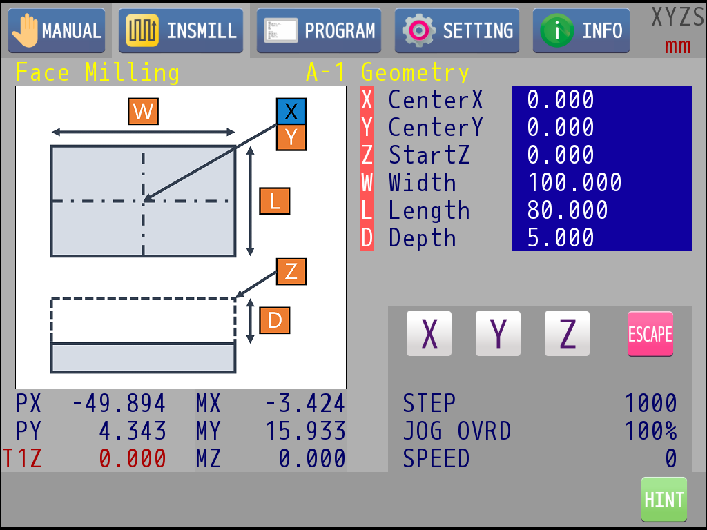
4.3 Object Editing Page
|
: |
Press key 2 to exit the object editing page and return to the INSMILL main page. |
|
: |
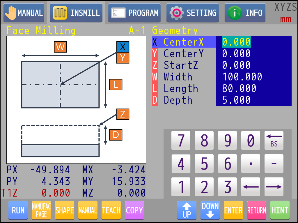
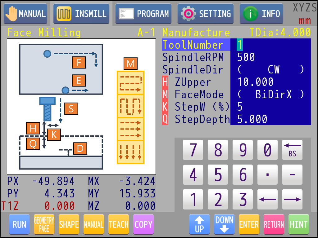
Press the knob to switch edit page between geometry parameters and manufacture parameters. The schematic diagram on the left will also change when switching. In the manufacture page, the tool diameter of currently selected tool number would show on the top of the parameter list. |
|
: |
Knob rotating could select the item to be edited. If there is an English character with red background in front of the item, user can find a corresponding hint in the schematic diagram on the left. The color of the hint would change when the item is selected. |
|
: |
If the parameter is numeric, it can be edited directly with the numeric keypad. |
|
: |
If there are brackets on the left and right sides of the parameter, it means that the parameter must enter the next level to do the selection, press key 1 to enter. |
|
: |
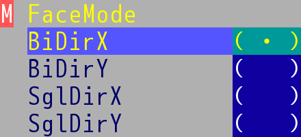
Take "Face Milling→Manufacture→M FaceMode" as an example, this selecting list will appear after entering. |
|
: |
Rotate knob or touch to select item. |
|
: |
Press key 1 to confirm the selection of current item and return to previous page. |
|
: |
Press key 2 to quit this operation and return to previous page, the parameter will not change. |
|
: |
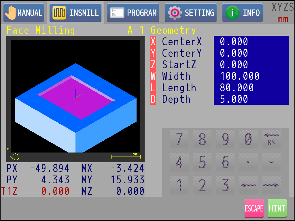
Touch "SHAPE" icon. The schematic diagram will change to the simulation display. Simulation can show the geometric appearance of the current editing and the relation between current object and the material. System would check if current editing is proper before it goes to simulation display. A prompt window would pop up if there is any problem with the parameters. |
|
: |
Press the knob is to change the viewing angle (XY plane, XZ plane, isometric view) |
|
: |
Knob rotating can zoom in and out. |
|
: |
Press key 2 to exit the simulation mode and return to the object editing mode. |
|
: |
Touch "MANUAL" icon below. It will enter the manual mode. In this mode, the numeric keyboard will be replaced by the manual operation panel, and the operation is the same as the manual page operation. |
|
: |
Take axis X as an example. Touch the axis icon. It means the axis is ready while the icon starts blinking. |
|
: |
Press key 1 and key 2 to move the axis in jog mode. |
|
: |
Rotate the knob to move the axis in a fixed step. |
|
: |
Press the knob to adjust the step and Jog override. |
|
: |
Touch "ESCAPE" icon to exit manual mode and return to object editing mode. |
|
: |
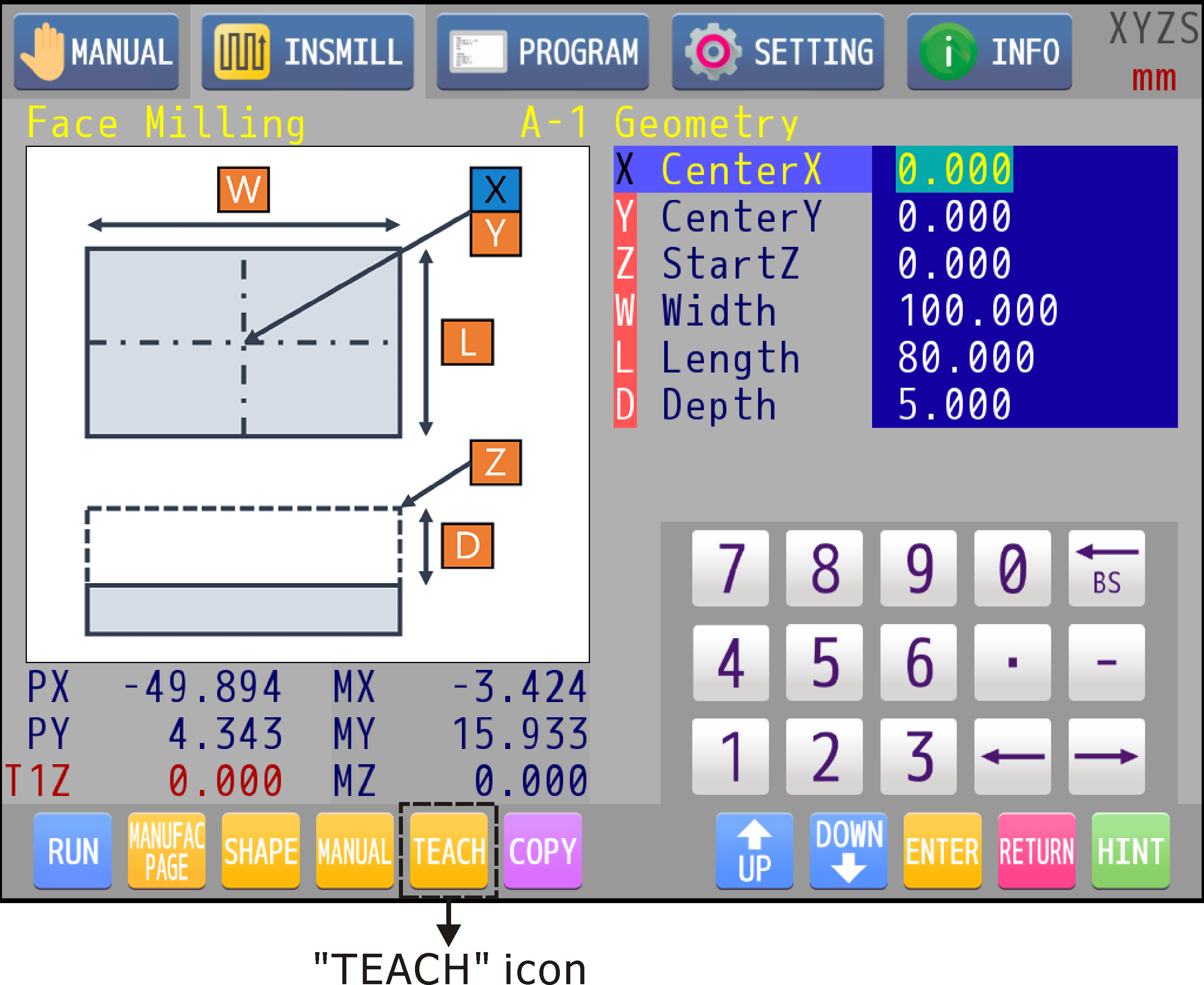
It is usually a combo using of Manual and Teach. Teach can put current program position value into the selecting parameter (the parameters related to the offset, X/Y/Z). Move the axes manually to the position to be taught, select the parameter to be filled in, and touch "TEACH" icon below. Current program position of the chosen axis will fill in the parameter. |
|
: |
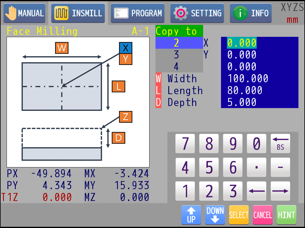
If you want to copy the parameters of current entity to another entity of the same object, you can touch "COPY" icon below. |
|
: |
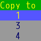
A copy-to dialog will pop up. |
|
: |
Rotate the knob or touch to select the target entity. |
|
: |
Press key 1 to copy. |
|
: |
Press key 2 to quit this operation. |
|
: |
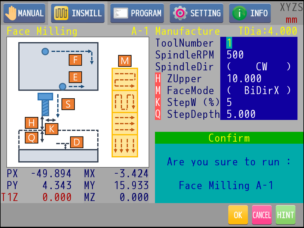
To execute the process object after editing, touch "RUN" icon. M83 will check whether the parameters are correct or not before executing the program. If it is correct, a confirm window will pop up. |
|
: |
Press key 1 to confirm execution. |
|
: |
Press key 2 to quit. |
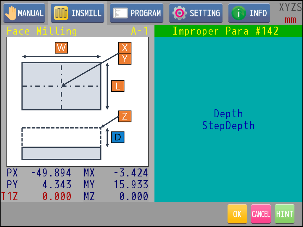
If the object is checked out with some improper parameter, M83 will pop up a window and show the items which are improper. User must check the parameters again and modify it until the program could be execute correctly.