2.3 Quick Operation Guide
Following will give an example of how to do manual operation, set the origin of program coordinate and program a INSMILL face milling:
Manual operation and setting the origin of program coordinate
|
: |
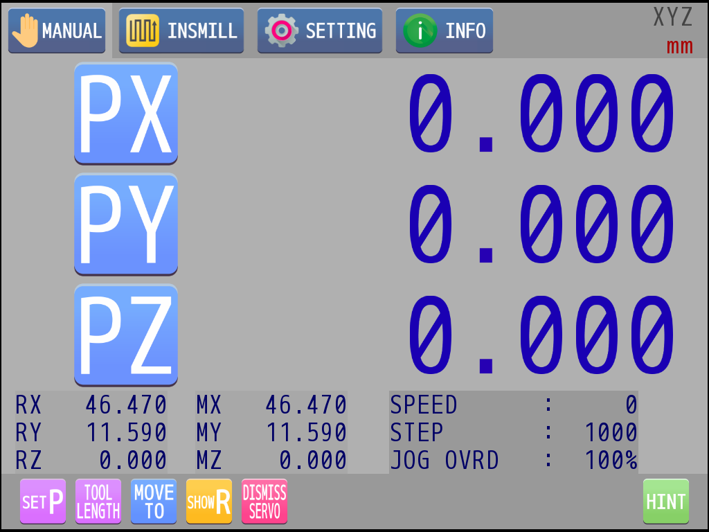
Touch manual tab to enter the manual page. |
|
: |
Take axis X as an example. Touch the axis icon. It means the axis is ready while the icon starts blinking. |
|
: |
Press key 1 and key 2 to move the axis in jog mode. |
|
: |
Rotate the knob to move the axis in a fixed step. |
|
: |
Press the knob to adjust the step and jog speed override. |
|
: |
When finish the moving, touch "SET P" icon below. |
|
: |
The axis-to-set dialog will pop up at this time. |
|
: |
Knob rotating or touch can select the axis to set. |
|
: |
Press key 1 to confirm the selection of desired axis. |
|
: |
Press key 2 to quit this operation. |
|
: |
If you select change axis X and press key 1, the dialog of program position modification mode will appear. If "=0" is selected, the current X-axis program position will be set to zero which means it is the origin of X. Repeat above steps to set program position of other two axes. |
Program INSMILL face milling
|
: |
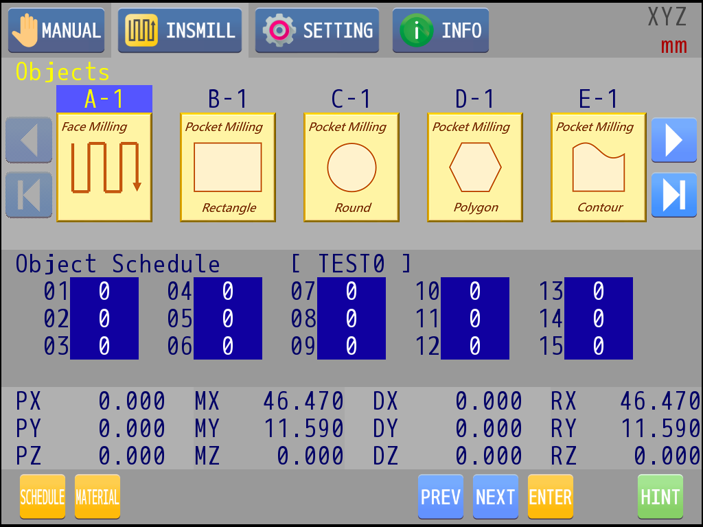
Touch INSMILL tab to enter the INSMILL page. |
|
: |
Rotate the knob or touch to select face milling object (A). |
|
: |
Press key 1 to confirm the selected object. |
|
: |
Object entity selection list will appear at this time. |
|
: |
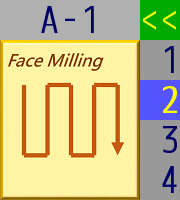
Rotate the knob or touch to select the object entity to be edited. |
|
: |
Press key 1 to enter the selected object editing page. |
|
: |
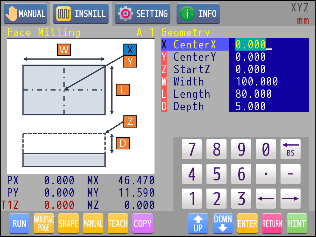
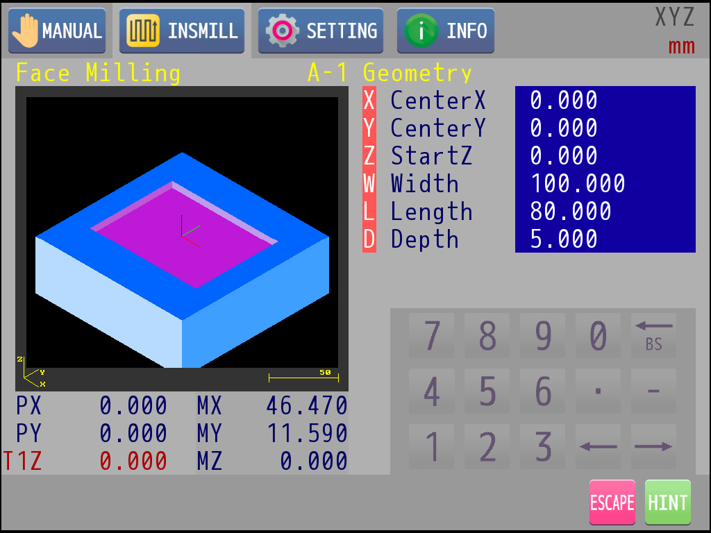
Press the knob to switch current edit page to geometry parameters or manufacture parameters. |
|
: |
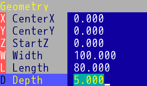
Knob rotating could select the item to be edited. If there is an English character with red background in front of the item, user can find a corresponding hint in the schematic diagram on the left. |
|
: |
If the parameter is numeric, it can be edited directly with the numeric keypad. |
|
: |
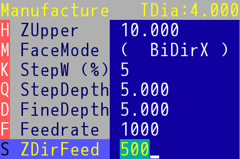
If there are brackets on the left and right sides of the parameter, it means that the parameter must enter the next level to do the selection, press key 1 to enter. |
|
: |
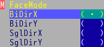
Take "Face Milling→Manufacture→M FaceMode" as an example, this selecting list will appear after entering. |
|
: |
Rotate the knob or touch to select item. |
|
: |
Press key 1 to confirm the selection of current item and return to previous page. |
|
: |
Press key 2 to quit this operation and return to previous page, the parameter will not change. |
|
: |
Fill in the geometry parameters. |
|
: |
Fill in the manufacture parameters. |
|
: |
Touch "SHAPE" icon below to enter the simulation. |
|
: |
Press Key 2 to exit the simulation and return to the object editor. |
|
: |
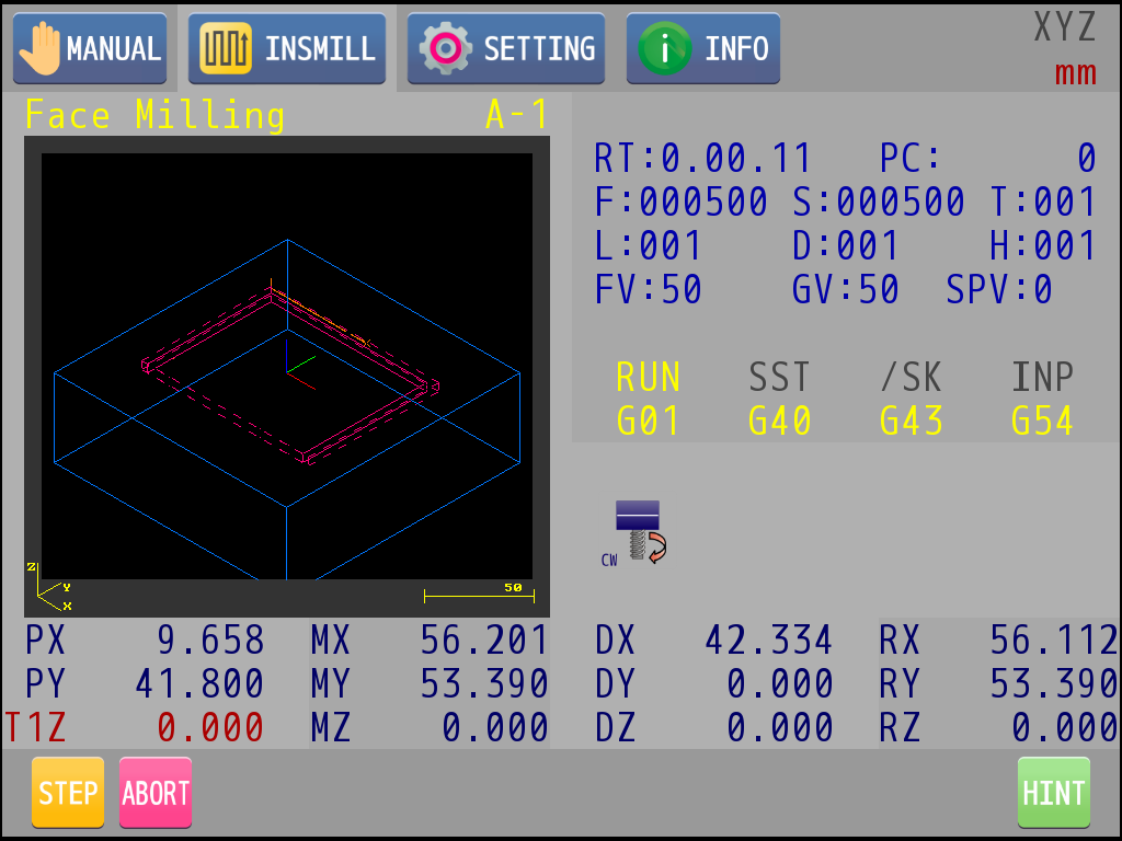
After confirming the editing parameters. If you want to execute this object, touch "RUN" icon in the auxiliary row. |
|
: |
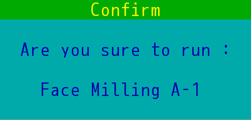
Before executing any INSMILL object, M83 will check whether the parameters are correct or not. If there is no improper data, a confirm window will pop up. |
|
: |
Press key 1 to execute it. |
|
: |
Press key 2 to quit. |
|
: |
If key 1 is pressed, the speed override dialog will pop up. |
|
: |
Knob rotating or touch can select the override to apply on the program. |
|
: |
Press key 1 to select current override and start processing. |
|
: |
Press key 2 to quit this operation. |

|
: |
During program execution, rotating the knob can modify the override. |
|
: |
Press key 2 to pause the program. |
|
: |
Press key 1 to continue the program. |
|
: |
Touch "STEP" icon to switch to single-step mode. Press key 1 to execute next step after every single step. |
|
: |
Touch "ABORT" icon to terminate the program. |