11.1 Position and Feed Commands
G00: Rapid Traverse
Format:
G00 X_Y_Z_
G00 initiates rapid traverse of tool to move from current program position to a specified program position X_Y_Z_. The traverse speed is the value of G00 speed in "Setting→Advanced→X/Y/Z Axis→Motion and Speed→G00 Speed" multiplied by G00 Feed Override %. G00 is a modal G code and remains effective until replaced by other motion G codes such as G01, G02, or G03. G00 can be 1-axis, 2-axis, or 3-axis simultaneous motion, the moving mode is Z axis first, and then X and Y axis.

G00 2-axis Positioning

G00 3-axis Positioning
Note: |
Under the circumstance of 2-axis positioning, G00 command are irrelevant to G17/G18/G19 plane selection. |
G01: Linear Interpolation
Linear Interpolation
Format:
G01 X_Y_Z_F_
When the outline of the workpiece is a straight line, it is cut by the G01 command. The X_Y_Z_ coordinate position is the cutting end point, while the F_ value designated cutting feed rate, the override adjustment can adjust the speed.
The unit of F_ differs as defined by G94 (mm/min) or G95 (mm/rev). F_ is the continuous effective instruction, so the next single section cutting rate can be omitted when omitted. For example: F0.1 S3000 feedrate in G95 mode: 0.1 (mm/rev) x 3000 (rev/min) = 300 (mm/min)

G01 2-axis Linear Interpolation

G01 3-axis Linear Interpolation
Note: |
That G01 is not related to the plane selection such as G17/G18/G19 for any two-axis linear interpolation. However, if the chamfering or rounding is required, the axis to be moved must be defined by G17/G18/G19 If the plane is the same, G17 must be G01 X_Y_L_F_ or G01 X_Y_R_F_, not G01 X_Z_F_. |
Linear Interpolation with Chamfered or Rounded Angle
Format:
G01 X_Y_L_F_
G01 X_Y_R_F_
Chamfering or rounding can only be performed in a specific plane, and both the chamfering or rounding of the line and the next line must be a linear interpolation command before chamfering or rounding is performed.
Chamfer is at a distance from the intersection of two straight lines L_ value of the distance, automatically add a chamfering instructions, so that the workpiece is not too chamfered angle. At the intersection of the two straight lines, the rounding automatically adds an arc command with a radius of R_, tangent to the arc with the two straight lines so that the chamfer of the original workpiece becomes a rounding.

Corner Rounding and Chamfering
Note 1: |
The chamfer's L_ value or the R_ value of the rounding must be an appropriate size, which is not executable if the two values are too large. |
Note 2: |
The linear interpolation of round and chamfer is related to the plane selection. Only X_Y_L_ (R_) can be executed under G17. Only Y_Z_L_ (R_) can be executed under G19 and only X_Z_L_ (R_) can be executed under G18. |
G02/G03: CW/CCW Circular Interpolation
• Definition of G02/G03
G02: Clockwise (CW) Arc cutting
G03: Counter clockwise (CCW) Arc cutting
The arc outline on the workpiece is cut by G02 or G03 command. Milling machine workpiece is three-dimensional, so in different planes of its arc cutting direction as shown below. The definition of the way: the line of sight toward the positive direction of the plane vertical axis to the negative direction, clockwise G02, counterclockwise G03. The path of arc interpolation varies with the selection plane, so G17/G18/G19 must be given before the single-block program.

Circular Directions and Plane Selection
1. Paths on the plane G02/G03 X_Y_, X_Z_, Y_Z_

G02/G03 Path on Different Planes
2. G02/G03 X_Y_Z_P_ Helical interpolation path in space

G02/G03 Path in Different Dimensions (Take G02 CW for Example)
• Format of G02/G03
format |
2D (Arc or circle) |
3D (Helical) |
Radius format |
G17 G02(G03) X_Y_R_F_; G18 G02(G03) X_Z_R_F_; G19 G02(G03) Y_Z_R_F_; |
G17 G02(G03) X_Y_R_Z_F_; G18 G02(G03) X_Z_R_Y_F_; G19 G02(G03) Y_Z_R_X_F_; |
Circle Center format |
G17 G02(G03) X_Y_I_J_F_; G18 G02(G03) X_Z_I_K_F_; G19 G02(G03) Y_Z_J_K_F_; |
G17 G02(G03) X_Y_I_J_Z_F_; G18 G02(G03) X_Z_I_K_Y_F_; G19 G02(G03) Y_Z_J_K_X_F_; |
Angle format |
G17 G02(G03) I_J_A_F_; G18 G02(G03) I_K_A_F_; G19 G02(G03) J_K_A_F_; |
G17 G02(G03) I_J_A_Z_F_; G18 G02(G03) I_K_A_Y_F_; G19 G02(G03) J_K_A_X_F_; |
Adding the Z_ and P_ values to the G02/G03 command line specifies the number of helical to perform helical interpolation.
format |
3D (Helical) |
Radius format |
G17 G02(G03)X_Y_R_Z_P_F_; G18 G02(G03)X_Z_R_Y_P_F_; G19 G02(G03)Y_Z_R_X_P_F_; |
Circle Center format |
G17 G02(G03)X_Y_I_J_Z_P_F_; G18 G02(G03)X_Z_I_K_Y_P_F_; G19 G02(G03)Y_Z_J_K_X_P_F_; |
Angle format |
G17 G02(G03)I_J_A_Z_P_F_; G18 G02(G03)I_K_A_Y_P_F_; G19 G02(G03)J_K_A_X_P_F_; |
1. Radius Format
Normal state: In the circular interpolation instruction, if any R_ value appears, it will be treated as if it is preferred. In the instruction, X_Y_Z_ refers to the destination, and R_ refers to the radius. When R_ is negative, the arc will be greater than 180 degrees.
Format: G02 (G03)X_Z_R_

G02/G03 Radius Format: Normal Tool Path
If d > 2R: If the value of R_ is less than half of the travel to the destination, a semicircle with R_ radius will be taken first, and then it will go straight to the destination. However, this circular instruction mode still remains valid.
Format: G18 G02 (G03)X_Y_R_

G02/G03 Radius Format: Tool path when d>2R
If R = 0: If only X_Y_Z_ is given and R = 0, it will go straight to the destination. If only G02/G03 is given and there is no X_Y_Z_ or R_ value afterwards, no action will be performed.

G02/G03 Radius format:G02 (G03)X_Y_Z_R0 or X_Y_Z_
2. Center Format
Normal state: In the instruction, X_Y_, X_Z_, and Y_Z_ refer to the destination, and I_J_, I_K_, and J_K_ indicate the distance of the center of the circle relative to the starting point in each axial direction. If I_J_, I_K_, and J_K_ are the actual arcs of the circle, the given destinations X_Y_, X_Z_, and Y_Z_ do not necessarily fall on the arc very accurately. In order to make the destination X_Y_, X_Z_, Y_Z_ fall on the arc, the center and radius of the arc will be recalculated. The new radius R′ is the average of the distance from the original center to the starting point and the end point, and then automatically changed. Circular interpolation for "radius format". As shown below, "e" is the distance between the target location and the center of the circle. (A) is normal. (B) is when e > R. (C) is when e < R.
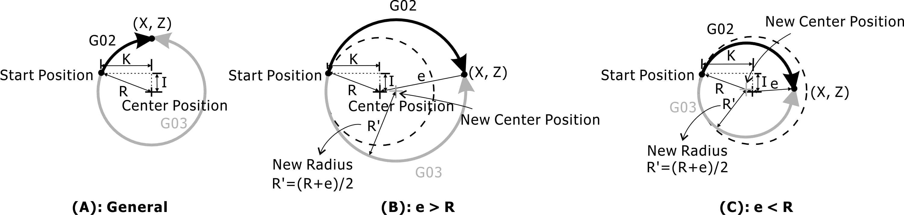
Tool Path of G02/G03 in Center Format (General)
If the destinations X_Y_, X_Z_, and Y_Z_ are not given, a full circle will be made with I_J_, I_K_, and J_K_ as the center. If the start point and end point in the G02/G03 instruction are the same, execute a full circle.

G02/G03 Center format: G02 (G03)I_J_
If X_Y_, X_Z_, Y_Z_ have given and I_J_, I_K_, J_K_ have zero values, they will go straight to the destination.
G02/G03 Center format: G02)(G03)X_Y_I_J_, X_Z_I_K_, Y_Z_J_K_ or G02 (G03)X_Y_, X_Z_, Y_Z_
3. Angle format
Normal state:When given A_ value, give center, A_ value as angle. This angle can be absolute or relative incremental.
Format: (A) G90 G02 (G03)I_J_A_, (B) G91 G02 (G03)I_J_A_

Tool Path of G02/G03 in Angle Format (General)
In the absolute coordinate mode, if only the A_ value is zero, the following actions will be performed.

G02/G03 angle format:In absolute coordinate mode, only A_ value is zero
In the absolute coordinate mode, if the center and angle values are zero, there will be no action. In the relative increment mode, if the center value is zero or the angle value is zero, there is no action.