6.7.1 X Axis (Y Axis, Z Axis)
Operate
Switch on servo enable signal only if the EtherCAT servo drives are wired properly and the parameters in "Advanced→Axis→Motor" is confirmed.
This setting could determine whether to operate the chosen axis or not. Switch it on, M83 will send the servo enable signal and velocity command to the drive through EtherCAT protocol. Vice versa, but it will still recieve position feedback through EtherCAT.
Mechanism
- Inverse Direction
This setting can make the axis moving in the inverse direction to fit the actual machine coordinate if needed.
- Feed Pitch
The distance that machine moves while the axial screw makes one turn.
- GearRatio Numerator
If there is a reducer between motor and the screw, set the numerator of the reduction ratio in this parameter.
For example: If double turns of motor makes the screw turn once, set this parameter to 1.
- GearRatio Denominator
If there is a reducer between motor and the screw, set the denominator of the reduction ratio in this parameter.
For example: If double turns of motor makes the screw turn once, set this parameter to 2.
- Backlash
Backlash means the tiny gap between the screw and the nut. It makes a slightly deviation while changing the axial direction. M83 could compensate this error. User should measure the backlash and set it in this parameter for the purpose of a more accurate using.
Motion & Speed
- Acceleration
Controller applies linear acceleration on G00 and JOG movement. This value indicates the duration for this axis to accelerate from 0 to 6000 mm/min, and the unit of the duration is 10 ms.
For example, if the acceleration setting is 10, it takes 10 × 10 ms = 100 ms to reach 6000 mm/min.
- Feed / Pos Loop Gain
Gain of the position control loop. The system responds faster and the lag error gets smaller as the gain goes higher. The system responds slower and the lag error gets bigger as the gain goes lower. A high loop gain can increase the tracking ability of the system and decrease lag error, but a high gain would lead to chatter if the transmission system isn't stiff enough.
The upper bound of "Feed Loop Gain" and "Pos Loop Gain" is 255. Users can set different value to them according to different scene. "Feed Loop Gain" is applied on the G01 feed, and "Pos Loop Gain" is applied on other situation including manual moving.
For example: A higher "Feed Loop Gain" could improve the performance and lower the error while running a program so that a high speed high accuracy control can be done. A lower "Pos Loop Gain" with a higher acceleration could make the system moving quickly without chatter while doing the rapid positioning or manual moving.
- In Position Width
"In Position Width" stands for a range around the desired position that system would take it as in-position. When there are consequent moving command lines, system would start moving toward next command once it is in that range but wait until it reach the actual desired position.
If set this value to 0, system will skip the in-position check. Unit of "In Position Width" is one quarter micrometer.
- G00 Speed
Speed of G00, unit: mm/min.
- Jog Speed
Speed of Jog, unit: mm/min.
Soft Limit
- Enable SoftLimit
After reset the machine position of this axis to 0, user could determine the boundary of both positive and negative directions. Select this function to enable the soft limit. Unit of soft limit is um.
Due to the limited size of the counter used to keep the position value in the drive, controller will take current setup of mechanical parameters and check if the counter in the drive would overflow within the boundary of soft limit after the soft limit is engaged. If yes, a warning will pop up. User could adjust the electronic gear ratio of the drive and reset the EncResObj of Motor parameters to prevent miscalculation while retrieving absolute position. Please check the setting of electronic gear ratio in 10.3.
The counter is a 32-bit signed integer. Assume there is a motor with 24-bit encoder which means 16777216 pulses output per round, a lead screw with 5000 μm pitch, and a reducer which turns 1 round at screw side while motor side turns 2. The overflow occurring position could be estimated by following relation:
![]()
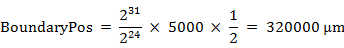
If "Positive SoftLmt" is greater than 320000 or "Negative SoftLmt" is lesser than -320000, it would make a miscalculation caused by overflow while retrieving absolute position outside the boundary. Regulate the encoder resolution to make sure it wont happen in the travel.
- Positive SoftLimit
The boundary in positive direction.
- Negative SoftLimit
The boundary in negative direction.
Motor
- VelCmdUnit
The unit of velocity command, which is object 0x60FF of COE driver. Please refer to the manual of servo drive to see if it is 1/10 rpm, 1/100 rpm or PULSE/S.
- EncResObj
This value is the resolution per round of object 0x6064 of COE driver. Please refer to the manual of servo drive. for example: if the motor uses 24 bits encoder and with no electronic gear ratio, this value shall be 16777216. Please check the detailed calculation in 10.3.
- RpmMax
Maximum RPM of this motor. Please refer to the manual of servo drive.
Reset Machine Position
Reset the machine position of this axis to 0 by applying this function. Please press emergency switch and then release it to check if the position has been reset correctly.