2.4 Machine Installation
Before you take out the i83 from the package, please refer to the following modes of use, and then prepare the necessary work tables.
The first use mode of i83: Workpiece processing within 300 mm × 200 mm × 30 mm stroke.
- Need to prepare a work table not less than 800 mm × 800 mm.
- It is necessary to prepare a plywood not less than 800 mm × 800 mm × 10 mm. This material is available in the wood material store, and it can also be cut on behalf of the customer.
1. |
Four long M4L10 round head woodworking screws (used to lock the machine on the plywood), screwdriver. or |
2. |
Four 40 mm × 100 mm × 10 mm plywood (for i83 embedded fixation) and 8 15 mm long iron nails and hammers. |
Fixing method with round head woodworking screws:
1. |
Put the 800 mm × 800 mm × 10 mm plywood flat on the work table. |
2. |
Take out the i83 and place it in the middle of the plywood. |
3. |
Use a screwdriver to lock the i83 onto the plywood. (There are long round holes on both sides of the i83 for easy locking with screws) |
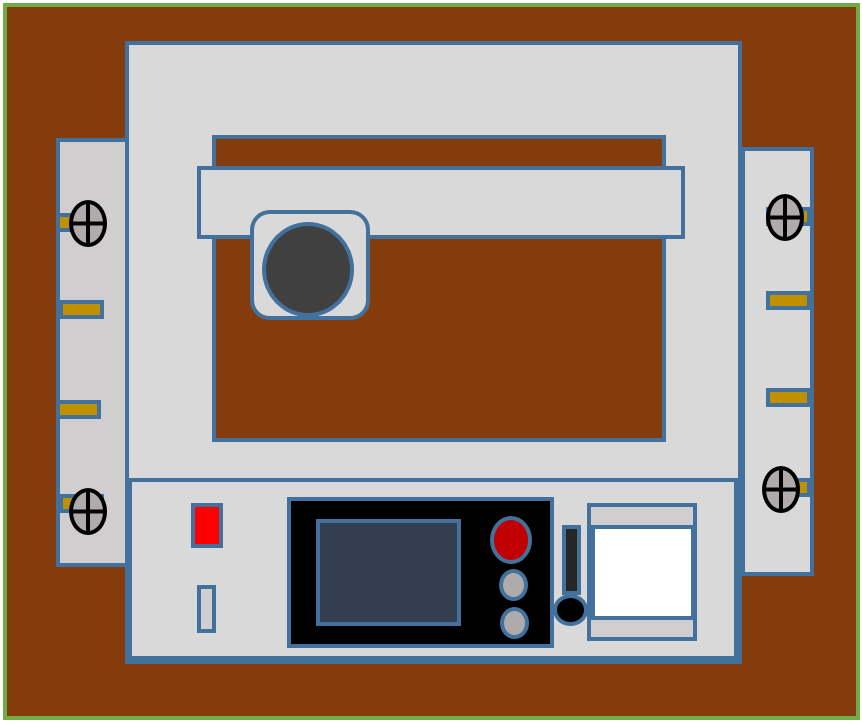
4. |
Use the INSMILL face milling object function of the M83 controller to set the milling depth of the plywood to 5 mm as the reference work surface. (Refer to the M83 controller manual, face milling function for the operation method). |
5. |
After completing the reference table, you can use 3M non-marking tape to fix the workpiece on the reference table for processing. (You can use the INSMILL object function or USB to download the processing program for processing.) |
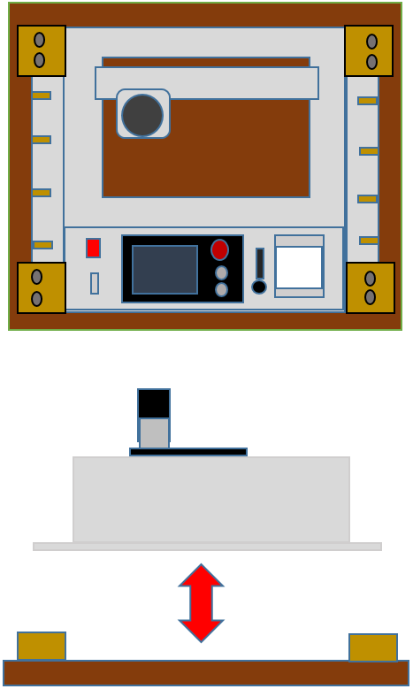
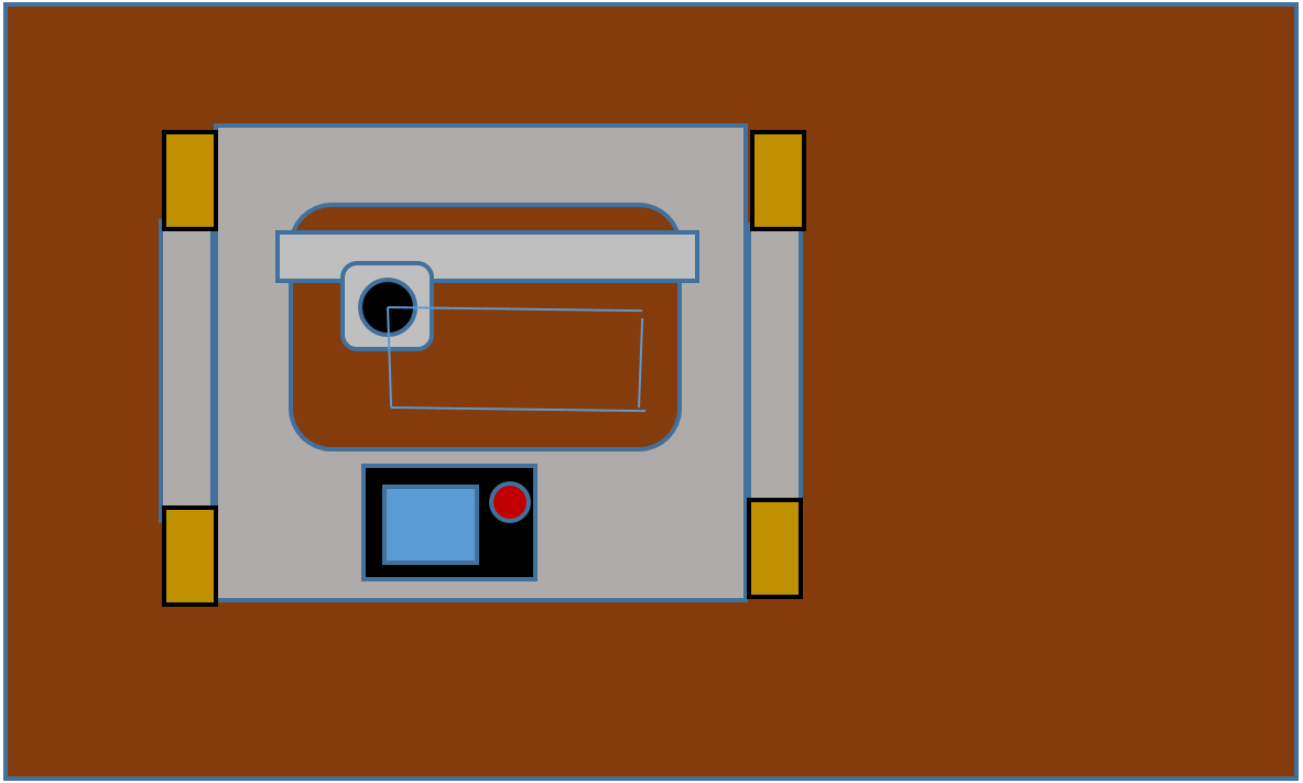
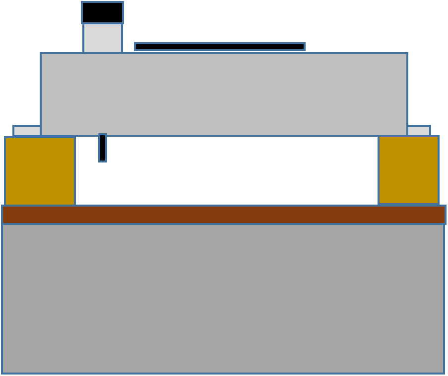
Use wooden blocks to embed i83 fixing method:
- Steps 1~2 are the same as using round head woodworking screws.
- 3 Put the wooden pieces in the four corners of the gaps on both sides of the i83. Use iron nails to fix the four pieces of wood on the plywood. The i83 can be easily inserted into or detached from the plywood.
- Steps 4~5 are the same as using round head woodworking screws.
The second use mode of i83: Machining in a large area of the seat (maximum 300 mm × 200 mm).
1. |
Place the workpiece on a stable and flat table or ground with a sufficient area. |
2. |
Use a pen to mark clearly the program dots on the part of the workpiece to be processed. For example, the upper left corner of the program origin requires two process areas. |

3. |
Put i83 on the workpiece, use the manual function to move the spindle to the maximum stroke point of the upper left corner of the i83 (assuming that the program origin and the mechanical origin are the same point, set this point as the program origin. If X, Y each deviate by 20 mm , Manually move the spindle to the upper left corner first, move down 20 mm in Y, move X 20 mm to the right, and set this point as the program origin. After the program origin is set, do not move the X and Y axes. |
4. |
Move the i83 machine to the position of the mark program origin, use the manual function to move the Z axis down to the workpiece plane, make sure that the position is correct and parallel to the X axis, set the program origin according to the program Z axis program origin (for example: workpiece plane Up 10 mm is the origin of the program Z-axis program. Manually move the Z-axis milling cutter up to 10 mm after touching the workpiece surface to set the origin of the program Z-axis program) |

5. |
Use a C-clamp to clamp the i83 to prevent it from sliding during processing, or use a wooden block (40 mm × 100 mm) and 3M non-marking glue to fix the i83 machine to prevent it from sliding. |
6. |
Perform processing. |
7. |
Remove the C-clamp or wooden block, move i83 to the next working area, and follow steps 1 to 6. |
The third mode: the thickness of the workpiece is greater than 30mm.
1. |
The method is the same as the first and second modes, except that the thickness of the bottom plate used is different. |
The fourth mode: completely open the workpiece by pushing it in from the side to fix it or pushing it in from the front to fix it.
1. |
The height of i83 should be about 80 mm, and i83 should be fixed firmly, not to slide or fall. |
Example: Push into the workpiece from the front.
2. |
After the workpiece is pushed in, the fixture must be fixed and not slippery. |
3. |
Carry out workpiece processing.。 |
4. |
Loosen the fixed clamp and withdraw the workpiece. |
Get ready for the above work, and then you can carry out the i83 power transmission, start, shut down, and emergency stop axial operation.
Power system:
i83 needs 600W single-phase AC 220V (3A) power supply. If your power plug meets the above specifications, you can follow the steps below to supply power to I83.
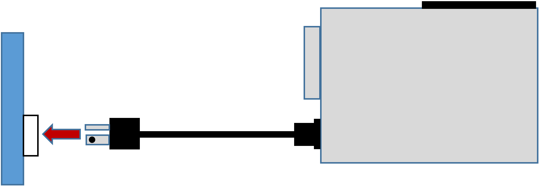
1. |
There is a power supply socket on the left side of the i83. Insert the power cord mother socket in the package into the power supply socket. |

2. |
Insert the plug of the power cord into the power outlet. |
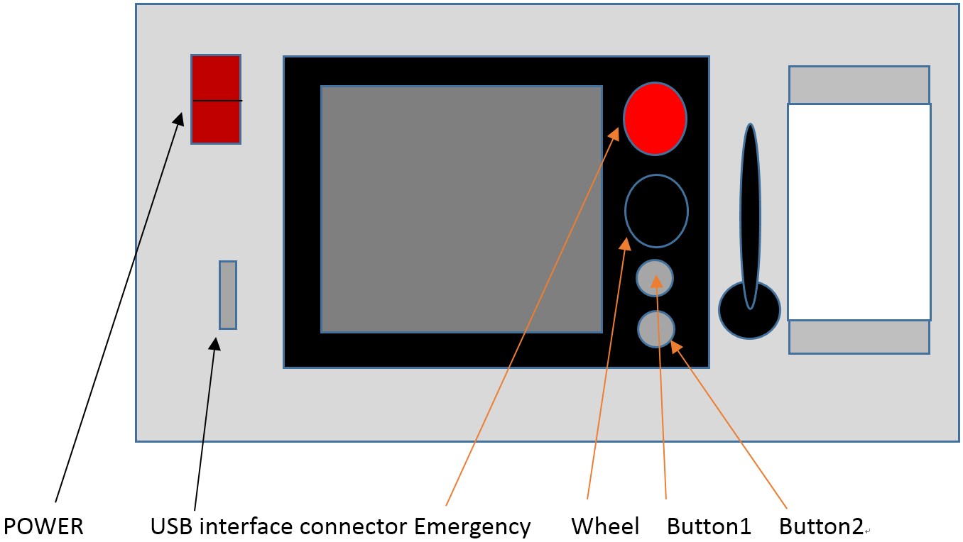
3. |
The i83 operation panel is equipped with a power switch, M83 controller, and USB interface connector. There is an emergency button on the M83 controller. |
4. |
Press the power switch to supply power to the i83, and the power switch will light up. |
5. |
Wait for a while. The M83 screen will display and an emergency switch alarm will appear (the AC servo motor will not be powered until the alarm is cleared, and the XYZ axis cannot be operated). |
6. |
Rotate the emergency switch to the right. The emergency switch will bounce up for a short distance. At this time, the emergency switch has been released and the XYZ servo motor starts to supply power. |
7. |
Press button 1 once to clear the alarm on the screen, and then you can operate i83. The i83 uses an absolute battery backup system and can be operated directly without resetting. |
If the power system is not single phase AC 220V, a transformer must be purchased.
- The power supply system is AC 110V. Purchase an AC 110V to AC 220V transformer.
- The power system is AC 380V. Purchase an AC 380V to AC 220V transformer.
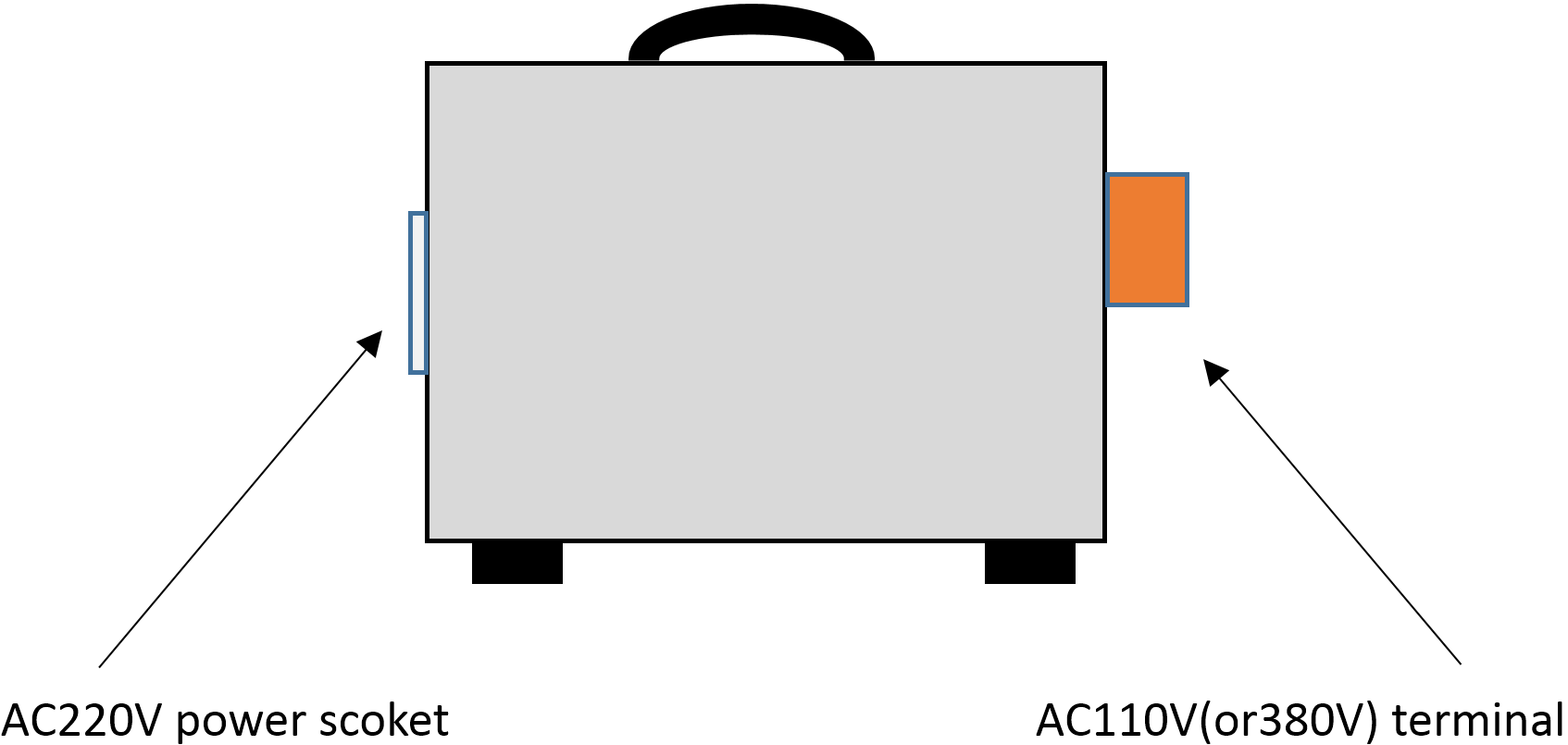
Intek Technology provides transformer options, which can be purchased.
Intek Technology's transformer option is a completely covered transformer, one end has terminal for connecting AC 110V (or 380V), and the other end is an AC 220V power socket.
1. |
First, use a power cord with a ground wire. There are three wires, two power lines and one ground wire. Connect in order according to the terminal label. Take 110V as an example. |
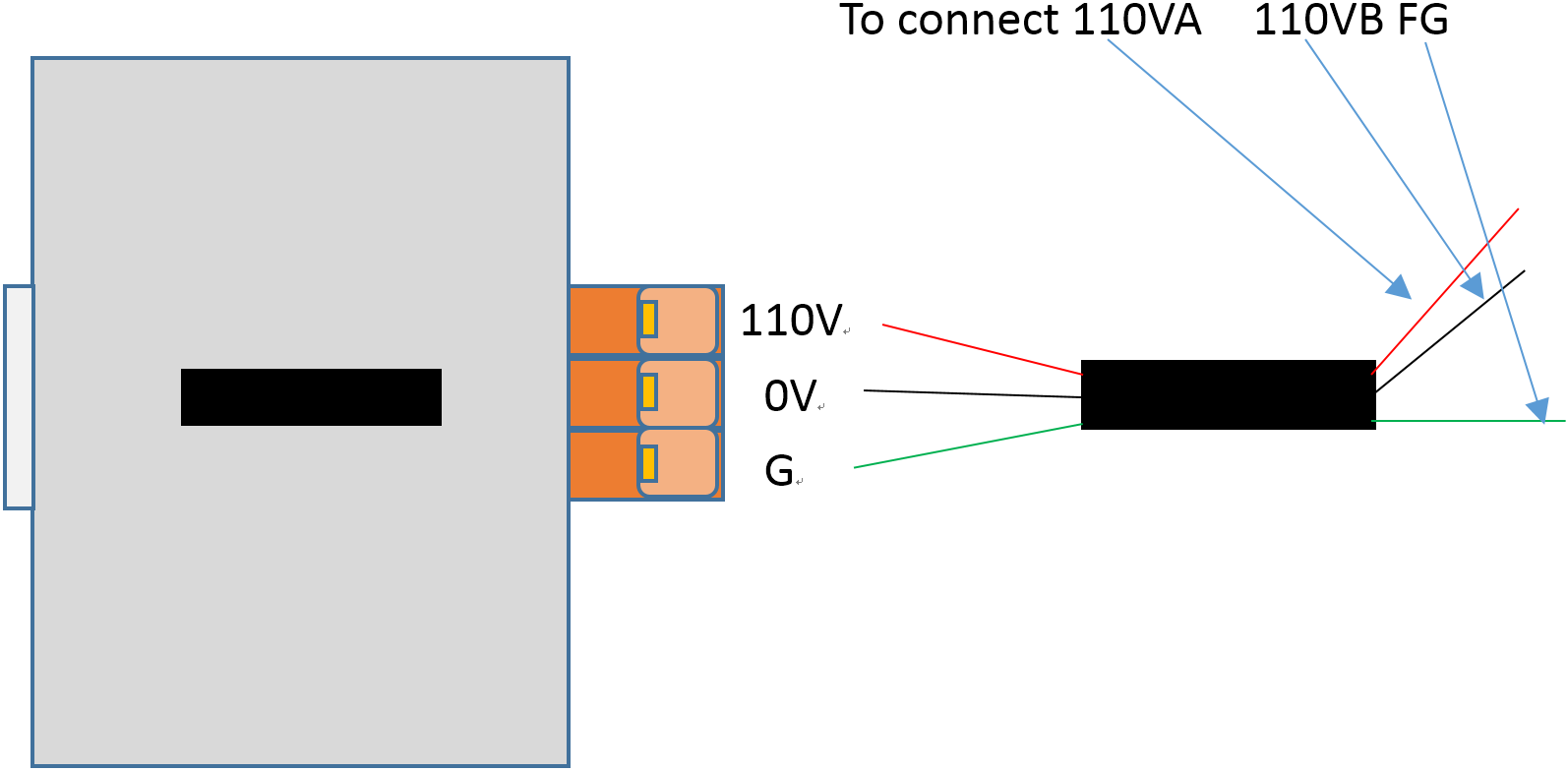
2. |
Insert the i83 power cord plug into the AC 220V socket of the transformer. |
Steps 3~7 are the same as the unused transformer.
For the spindle part, please configure the power supply and use method according to the spindle specifications and instructions.
The following example is the AC 110V woodworking WOODEN ROUTER:
1. |
Loosen the spindle holder into the wooden router to lock the spindle. |
2. |
Use the wooden router to install the tool. |
3. |
Please make sure that the switch of the wooden router is off, and the switch is on the upper part of the wooden router. |

4. |
Insert the power plug of the wooden router into the AC 110V socket. |
5. |
The wooden router is very noisy. Please wear noise-proof earmuffs and goggles. |
6. |
Turn on the wooden router for trial operation. If it is operating normally, turn it off. |
7. |
Please turn on operation before cutting, and turn off operation after cutting. |
Vacuum cleaner tube socket:
There is a vacuum cleaner tube socket next to the i83 spindle holder. Please insert the vacuum cleaner tube directly, and the suction tube should face the back of the machine to facilitate axial movement.
The i83 is a processing machine, so please do not put any part of your body into the cutting work area during cutting. If you violate the safety regulations, please be responsible for it, and the supplier of this equipment will not be responsible.
Shut down:
1. |
Turn off the spindle.。 |
2. |
Press the emergency button. |
3. |
Turn off the power switch. |
Absolute position backup battery replacement:
There is an absolute position backup battery box on the right side of the i83. The battery needs to be replaced in about 2 to 3 years. The battery must be powered when replacing the battery to prevent the absolute position from being lost. If you need to purchase batteries, please contact our company.
Please be sure not to operate the machine and open the spindle during the battery replacement process.
1. |
When i83 is powered on, use a screwdriver to open the battery compartment cover. |
2. |
Unplug the battery connector from the battery box connector and take out the battery. |
3. |
Insert the new battery connector into the battery box connector. |
4. |
Place the new battery in the battery box. |
5. |
Use a screwdriver to lock the battery compartment cover. |
6. |
Complete battery replacement. |
External connection control:
There is an I/O connecting box on the right side of i83. It provides spindle on/off output, tool probing input and two sets of I/O handshake M code contacts.
1. |
When the spindle starts the output point, the M83 controller executes M03 output conduction, and executes M05 output non-conduction. |
2. |
Measuring knife input, when the tool touches the measuring tool, it will be turned on, and if it is not touched, it will not be turned on. |
3. |
I/O handshake M code A. Call M10 in the program, output will be turned on and wait for the input. Once the input is on, output will be turned off. Then the M code will be finished when the input is off. |
4. |
I/O handshake M code B. Call M11 in the program, output will be turned on and wait for the input. Once the input is on, output will be turned off. Then the M code will be finished when the input is off. |
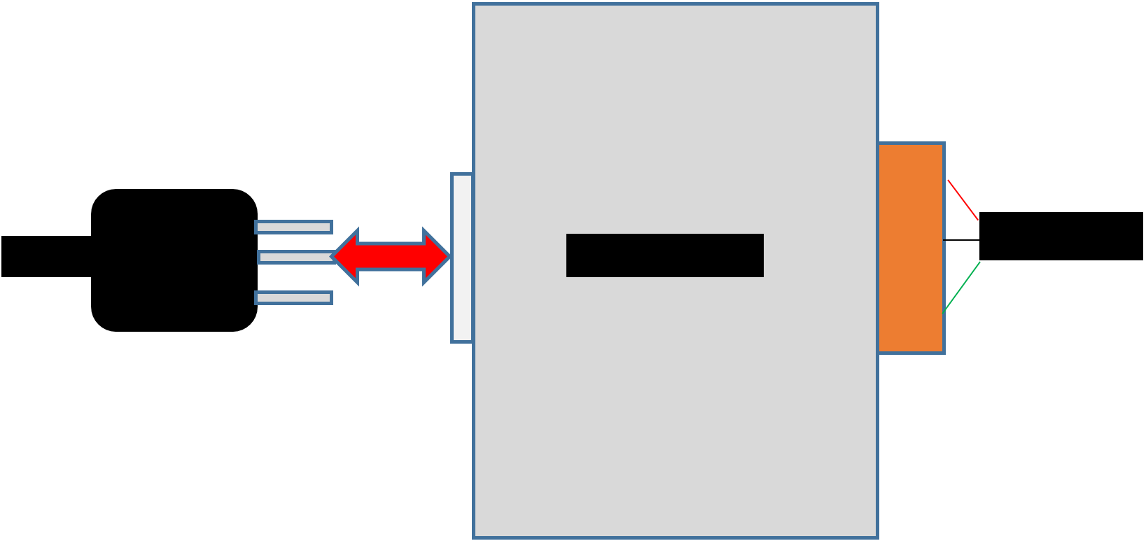
External connection terminal circuit board and connection method: The following wiring must be turned off in the power supply state.
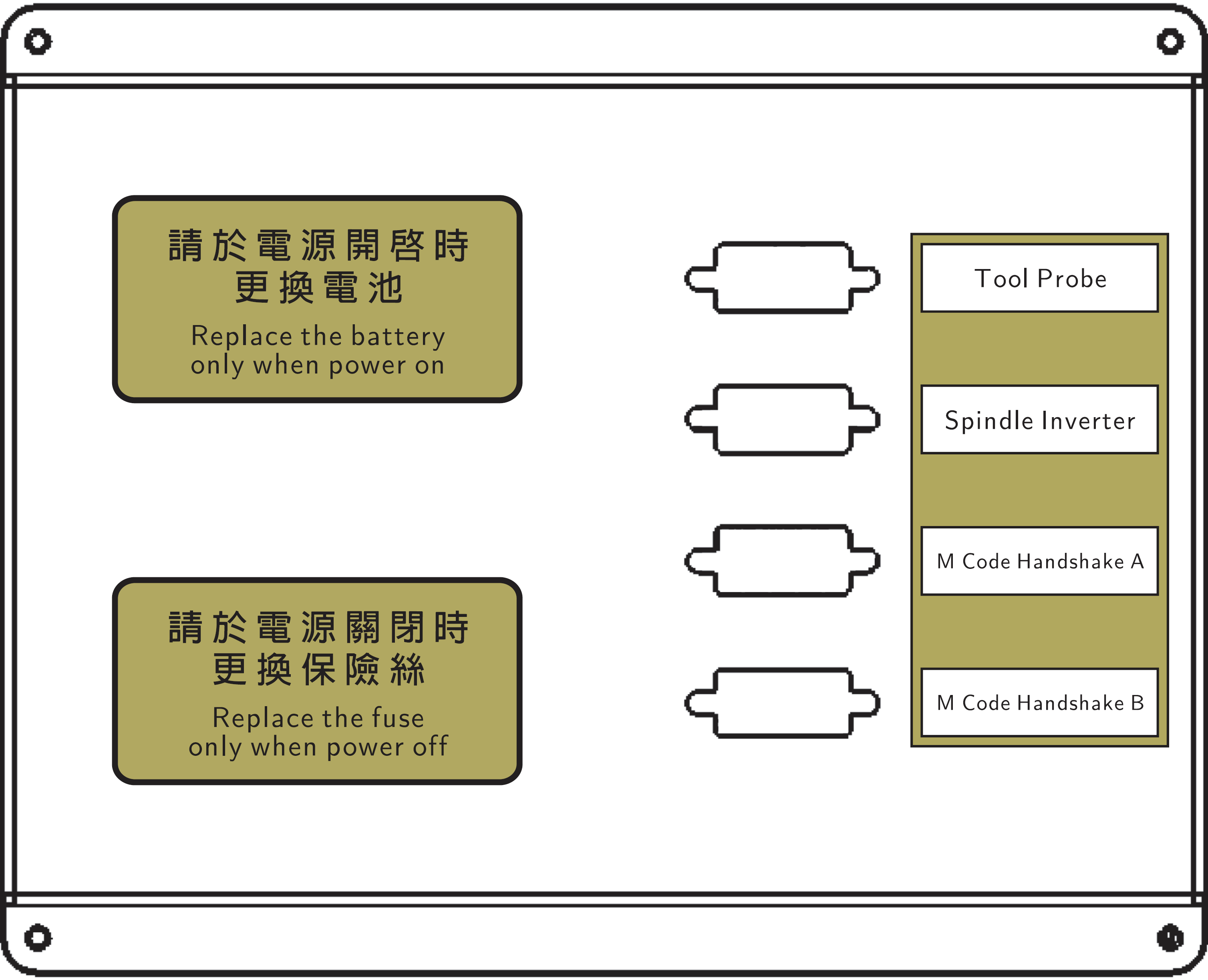
Signal definition:
Tool Probe(D-Sub)
Pin1 |
:the input point of the measuring board. |
Pin2 |
:The input points are common. |
Spindle Inverter(D-Sub)
Pin1 |
:M3 output +, collector (COLLECTOR). |
Pin2 |
:M3 output -, emitter (EMITTER). |
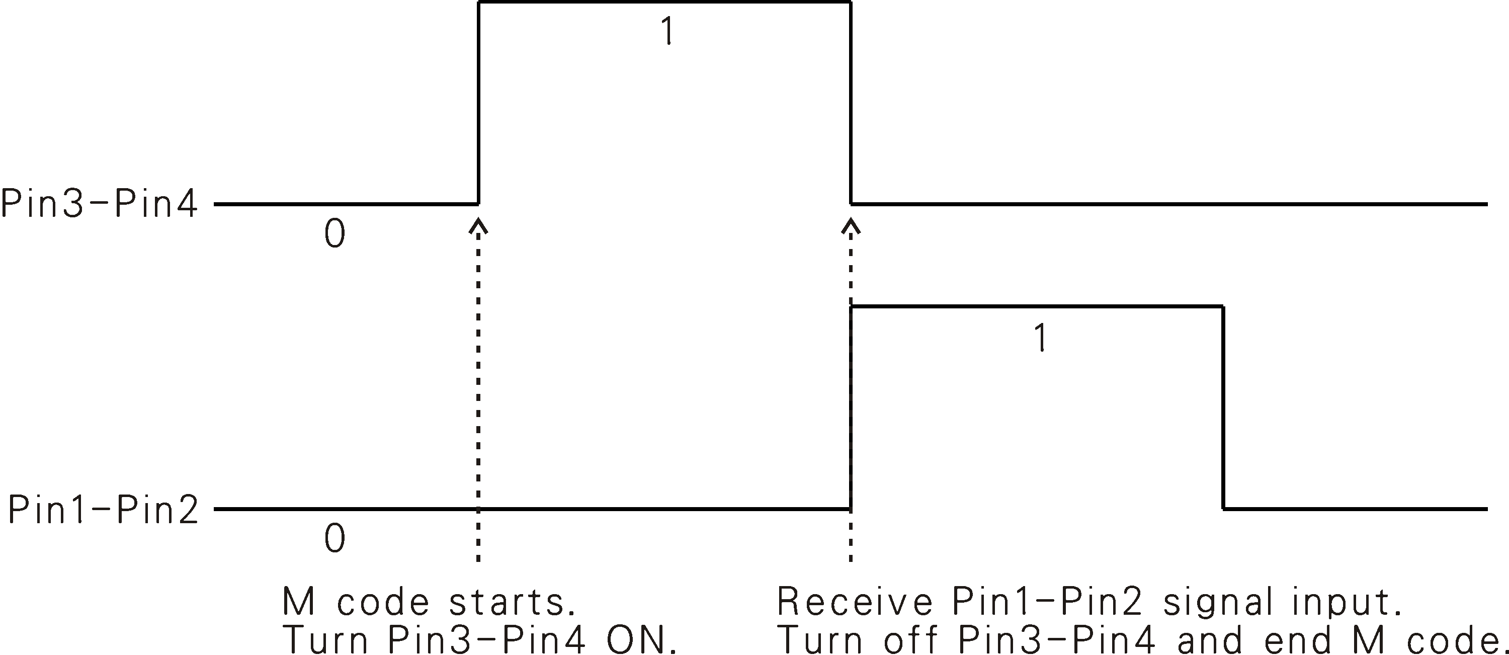
M Code Handshake A(D-Sub)
Pin1 |
:I/O exchange M code input point. |
Pin2 |
:The input points are common. |
Pin3 |
:I/O exchange M code output +, collector (COLLECTOR). |
Pin4 |
:I/O exchange M code output -, emitter (EMITTER). |
When the controller executes the command of M10, the Pin3-Pin4 output contact will be turned on, and after the Pin1-Pin2 input contact is turned on, the Pin3-Pin4 output contact will be closed and end at the same time M code and execute next line instruction.
M Code Handshake B(D-Sub)
Pin1 |
:I/O exchange M code input point. |
Pin2 |
:The input points are common. |
Pin3 |
:I/O exchange M code output +, collector (COLLECTOR). |
Pin4 |
:I/O exchange M code output -, emitter (EMITTER). |
When the controller executes the command of M11, the Pin3-Pin4 output contact will be turned on, and after the Pin1-Pin2 input contact is turned on, the Pin3-Pin4 output contact will be closed and end at the same time M code and execute next line instruction.
Both input and output have LED indicating status, and the opposite LED will light up when there is an input relative to the input. The LED that has output relative to the output will light up.
I1 |
LED1 |
O1 |
LED5 |
I2 |
LED2 |
O2 |
LED6 |
I3 |
LED3 |
O3 |
LED7 |
I4 |
LED4 |
O4 |
LED8 |
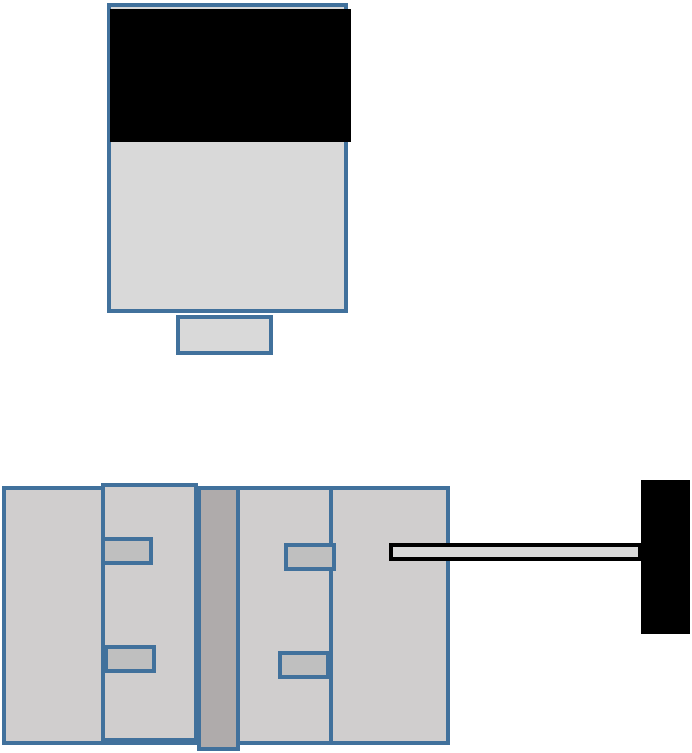
Measuring tool board
i83 comes with a measuring tool board for the convenience of users to measure the distance between the tool and the workpiece plane. This measuring tool board is a consumable item. If the measuring tool surface is unusable, you should purchase a new one. There is an LED on the measuring knife board. When the LED is lit, the tool has touched the measuring tool board.
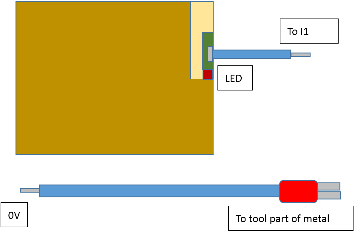
Wiring:
Use i83 to supply 24V.
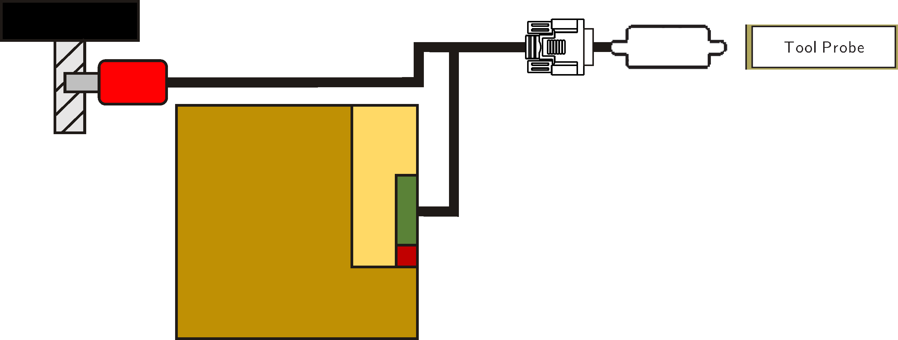
Usually when the tool reaches the measuring tool board, the thickness of the cutting board at this position is the workpiece plane position, for example: measuring tool board thickness: 2mm, the measuring tool board is placed on the part plane, the Z axis hand moves the Z axis manually to touch the measuring tool board (The LED of the measuring knife board is lit). At this time, if the program coordinates: 35.000, the mechanical coordinates: -45.000, the workpiece plane program coordinates: 33000, and the mechanical coordinates: -47.000.
If there are any unclear points during the installation process, please contact local distributors or INTEK Technology.