9.13 Contour Side Milling
Contour side milling means a down cutting to designated depth move toward a user-defined closed contour.

Geometry
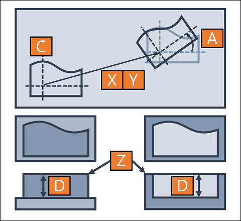
X CenterX |
The distance from the origin of workpiece to the origin of the contour in X direction. |
Y CenterY |
The distance from the origin of workpiece to the origin of the contour in Y direction. |
Z StartZ |
The distance from the origin of workpiece to the upper surface of removed area in Z direction. |
C Contour |
User-defined contour. |
D Depth |
Depth of removal. |
A Rotate |
A counterclockwise rotation around the origin of the contour with designated angle. |
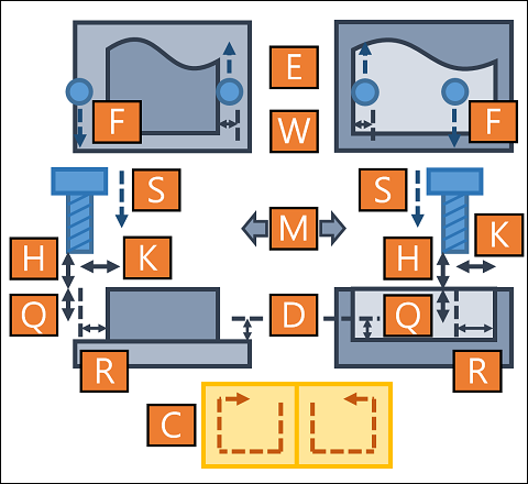
Manufacture
ToolNumber |
Order of desired tool in tool table. |
|
SpindleRPM |
Rotating speed of spindle. |
|
SpindleDir |
CW |
Spindle rotates in CW. |
CCW |
Spindle rotates in CCW. |
|
H ZUpper |
Z axis would halt at this position which is related to StartZ before and after cutting. |
|
C CutDir |
CW |
Direction of cutting route is CW. |
CCW |
Direction of cutting route is CCW. |
|
M SideMode |
OutsideIn |
Cut along the outer side surface. |
InsideOut |
Cut along the inner side surface. |
|
R RemovalW |
Width of removal. |
|
K StepWidth |
Width per cut. Must less than the diameter of selected tool. Set in percentage of tool diameter. |
|
Q StepDepth |
Depth per cut. Must less than or equal to Depth of geometry. |
|
W FineWidth |
Width of fine cut. Set to 0 if none. Must less than or equal to StepWidth, tool radius and RemovalW. |
|
D FineDepth |
Depth of fine cut. Set to 0 if none. Must less than or equal to StepDepth. |
|
F Feedrate |
Feedrate of XY moving. (mm/min) |
|
S ZDirFeed |
Feedrate of Z moving. (mm/min) |
|
E FineFeed |
Feedrate of fine cut. (mm/min) |
|
Note: |
The entry point is defined by the geometry and the removal width. The first cutting would make the tool center moving along the edges of removal width. There is no limit for the removal width when SideMode is OutsideIn. Otherwise, the removal width must less than the distance from center to the geometric boundary when SideMode is InsideOut. |